Thursday, December 12, 2019

New EXORBus ATX Power Backplane

I recently designed this backplane/extender/ATX power injector for EXORBus:

The rendering does not show the card edge connectors that will be populated on the board. Hopefully, I can get the PCB produced some time in the near future. Please post a comment if you are interested, and would like me to order an extra for you. ~$30.

Monday, July 29, 2019

CMS 9619 SUCCESS!

With the the power and serial port breakout boards hooked up, I tried turning on the CMS 9619, with no luck- nothing from the serial ports. The ROM I received with the unit is set up to run some user code on the second ROM at start-up, skipping the debugger. So, I made a patch to the ROM to make sure that the reset vector points to the debugger init code. The update has now been committed to the CMS_SBC GitHub code archive.

Unfortunately, this 2 byte change took several hours to get into an EEPROM, since I only have my Apple IIe and a Super Serial Card (SSC) to use as an EEPROM programmer. I had to make some changes to the BASIC EEPROM programmer script (Read More to see the program). I modified it so that it allows me time to switch in each 2K bank of the 8K EEPROM. Then I made the mistake of trying to upload the hex dump using a terminal connection to the Apple IIe (using another SSC with the standard ROM). Even at 19.2K bps, it took over an hour due to an overly conservative text pacing setting. I'm not sure why it took so long, but, of course, I soon realized that I had forgotten to move the jumpers to allow the programmer SSC to write to the EEPROM. The jumpers where located under my bank-switching adapter board, so I had to shut everything down to reach them. Then I discovered an off-by-one error in the BASIC code and had to start the upload over. Switching to the method I previously described by using c2t to encode the ROM hex dump, then using the Apple //e's cassette input port made things go MUCH faster.

Slow serial upload to Apple IIe System Monitor

After installing the new ROM and powering on the CMS SBC, I still did not get anything from the serial ports. Some voltage testing led me to discover that the +12V was not making it to the RS232 receivers. I had hooked up the power to an ambiguously marked (and fortunately unused) pin 'U' rather than pin 'T' on the extension board.
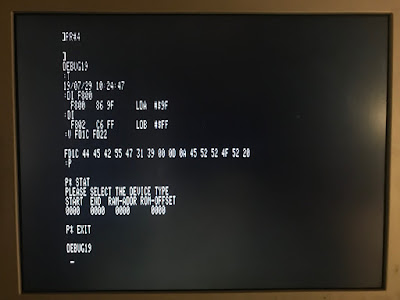
With power now going to all the right places, I was shocked to be greeted by:
DEBUG19 :
It worked! But it did not seem to be accepting any input. As it turns out, my wiring to the serial port adapter was slightly wrong in implementing a cross-over cable. After referring to a nice diagram online, and moving my Carrier Detect lines, it started accepting input!
APPLE IIe terminal connection to CMS 9619

Here are some of the commands I had a chance to disassemble and use ("H" is a hex digit):

  • R - Display the 6809 registers.
  • P - Enter the EPROM programmer.
    • STAT for status.
    • EXIT to quit.
  • T - Show the time from the RTC.
  • S - Set the time for the RTC. Format: "S YYMMDD HHMMSS"
  • E - Edit Memory. Format: "E HHHH"
    • Responds with "HHHH HH"
    • Enter: "HH" to set the hex value in memory.
    • [space key] for next byte.
    • "-" to go back a byte.
  • V - View Memory. Format: "V HHHH HHHH"
  • M - Move Memory. Format: "M HHHH HHHH HHHH", Source, Destination, Length.
  • G - Go to Memory (run). "G HHHH"
  • C - Clear Memory. Format: "C HHHH HHHH"
  • DI - Disassemble Instruction. Format: "DI HHHH", subsequent DI disassembles next address.
  • DB - Disassemble Block. Subsequent DB disassembles next block.

I very happy that this finally worked. It goes to show how useful an old Apple II is: I used a Centronics printer card to figure out the scheme of the PAL address decoder, a Super Serial Card to download the EPROMs and program the EEPROMs, and settled on the cassette input port to upload data. Now, to figure out something useful to do with the MC6809 SBC!

Check out all of the related blog posts for more details.

Sunday, July 21, 2019

CMS 9619 SBC Power and Serial Ports

Power

I don't have a proper card cage for a micromodule system, and clipping power leads to the card edge seemed a little sketchy, so I created a power supply connection to the CMS SBC board using:

  • CMS 9630 EXTENDER board (came with the 9619)
  • ATX power supply (had it in my parts bin)
  • ATX breakout board ($5-10 on ebay)
  • wires, test clips, and terminals (~$5 from my local surplus store)

After everything is connected up, here it what it looks like:
ATX breakout, extender board, and CMS 9619 SBC

This is probably overkill as the only thing that uses the ±12V are the RS232 transceivers which would probably run fine with ±5V

Serial Ports

After struggling with how to get standard DB9 serial ports from the randomly placed signals in the CMS SBC's 26 pin header, I decided to build a small breakout board ("BOB") to handle the conversion. It has: 26 pin IDC -> BOB -> dual DB9 IDC connectors. Then I did all of the wiring re-organization on the BOB with some point-to-point soldering. 26 pin P2 to DB9 adapter board

Friday, May 24, 2019

CMS SBC ROM Disassembly

Continuing my reverse engineering efforts on my CMS 9619 and 9609 SBCs, I downloaded the ROMs that were still in two of the boards. I inserted the ROMS into an Apple IIe's Super Serial Card (SSC) ROM socket, and transferred the data using the Apple IIe hardware monitor. I used a similar technique previously to program EEPROMs on the Apple IIe. However, since these are 8K ROMs, rather than the SSC's 2K ROMs, I had to solder up a little adapter board with two switches to switch in each 2K bank.

27C64 on adapter in Apple SSC27C64 adapter back side

With the ROM data in hand, I began machine code disassembly. Unfortunately I don't know 6809 assembly code, but with the help of the source code from an earlier version that I found online, I was able to figure out a lot of it. I started a new CMS_SBC GitHub project to keep the code in. It includes a makefile that translates the original Apple IIe monitor dumps into a hex dump, then a binary, then disassembles it.

Also, DaveW was kind enough to scan and post his documents for a CMS 9639 SBC that he has. It is more advanced than the 9609 and 9619 that I have, and includes an MMU. Great information there that I will need to spend some time looking at.

Friday, May 10, 2019

CMS 9619A SBC

I recently came into possession of a CMS 9619A Advanced Single Board Microcomputer. I have been unable to find any authoritative information on the device, but from what I can tell, it appears to be a Programmable Logic Controller for industrial applications. It features:

  • Motorola 6809 processor - 2 MHz MC68B09
  • 3* 6821 PIA - 2 MHz MC68B21
  • 1* 50 pin header for PIAs
  • 1* 6840 PTM - 2 MHz EF68B40
  • 2* 6551A ACIA - S6551A
  • 1* 26 pin header for ACIAs & PTM
  • 5* DIP28 RAM/ROM sockets
  • Motorola "EXORbus" compatible

The board was apparently made by Creative Micro Systems which was based in Los Alamitos, California (thanks for the info DaveW). There are a number of accessory boards available, and even some early MC6800 boards that I have seen. If anyone has more information about the board, please leave a comment!

Consumer retro-computer products are the subject of massive amounts of online data, scanned manuals, and schematics, but industrial controllers have very little information available on them. Probably a lack of nostalgia or general interest combined with continuing trade secrets. But this board looks like a very capable SBC just waiting to be put to good use. So, some reverse engineering is in order. I have been saving my notes in a Google Sheet available for public view.

Serial Terminal

I think that my best chance to figure this thing out is to connect to the serial port and see if there is an interface available there. Unfortunately, the 26 pin header is not a standard DB25 header for a RS232 connection. After much continuity testing, I finished the serial/timer header pinout, which is basically:

             P1 HEADER
              ______
U27-9  CTS2  |1    2|  DCD2 U27-16
U27-11 DTR2  |3    4|  RxD2 U27-12
U26-11 DTR1  |5    6|  DSR2 U27-17
U26-17 DSR1  |7    8|  TxD2 U27-10
U26-12 RxD1  |9   10|  RTS2 U27-8
U26-16 DCD1  |11  12|  TxD1 U26-10
U26-9  CTS1  |13  14|  RTS1 U26-8
       GND   |15  16|  GND
U28-7  C3    |17  18|  GND
U28-6  O3    |19  20|  C1   U28-28
U28-5  G3    |21  22|  O1   U28-27
U28-2  G2    |23  24|  G1   U28-26
U28-3  O2    |25  26|  C2   U28-4 
             |______|

Memory Map

The CMS 6919A has a PAL IC at U12 which decodes the addresses and enables the ROM and I/O ICs at the right time. I don't have the hardware to properly reverse engineer this PAL. But, I don't really need all of the details of the PAL, just the addresses when it enables most of the ICs. I do have an Apple II APIO printer interface card which sports its own 6821 PIA, and a "General" interface to all of the PIA's pins, which should work nicely to help decode it.

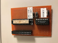
I soldered up a small carrier for the PAL and a binary counter IC to deal with the high address lines since I only have 8 output bits, and the PAL accepts 11 address lines (A5-A15). I also needed to add some switches to disable the PAL until the PIA is set up properly to avoid bus contention. Without that, the PAL gets hot! (Notice the brown burn mark on its paper label.) I wrote a BASIC program to run through all the possible address combinations for the PAL inputs, and list the PAL outputs, printing everything out in a nice layout. When an output from the PAL changes, the BASIC program adds a separator to the map and prompts for me to input the name of IC that the corresponding line is connected to.

Next, I had the program (not connected to hardware) run through the various addresses to the secondary decoder (U10) connected to the PAL to make a map of the I/O address space.

After paste-ing the files side-by-side on my Mac, here are the results:


                  MEMORY MAP                            I/O MAP
         |____________________________|          |____________________________|
0000:    |                            | FFC0:    |                            |
         |        > RAM               |          |        > U12 IRQ VECTOR    |
         |                            |          |____________________________|
         |                            | FFC4:    |                            |
         |_  _  _  _  _  _  _  _  _  _|          |        > U31 6821 PIA      |
         |                            |          |____________________________|
         |                            | FFC8:    |                            |
         |                            |          |        > U30 6821 PIA      |
         |                            |          |____________________________|
         |_  _  _  _  _  _  _  _  _  _| FFCC:    |                            |
         |                            |          |        > U29 6821 PIA      |
         |                            |          |____________________________|
         |                            | FFD0:    |                            |
         |                            |          |        > U27 6551 ACIA     |
         |_  _  _  _  _  _  _  _  _  _|          |____________________________|
         |                            | FFD4:    |                            |
         |                            |          |        > U26 6551 ACIA     |
         |                            |          |____________________________|
         |                            | FFD8:    |                            |
         |_  _  _  _  _  _  _  _  _  _|          |        > U28 6840 PTM      |
         |                            |          |____________________________|
         |                            | FFDC:    |                            |
         |                            |          |        > U28 6840 PTM      |
         |                            | FFDF:    |____________________________|
         |____________________________| 
A000:    |                            |               \                   /
         |        > U17 ROM           |                \_________________/
         |                            |                         |
         |                            |                         |
         |____________________________|                         |
C000:    |                            |                         |
         |        > U13 ROM           |                         |
         |                            |                         |
         |                            |                         |
         |____________________________|                         |
E000:    |                            |                         |
         |        > U7 ROM            |                         |
         |                            |                         |
         |                            |                         |
         |____________________________|                         |
FF80:    |                            |                         |
         |        > External I/O      |                         |
         |____________________________|                         |
FFC0:    |                            | \                       /
         |        > I/O               |  |_____________________/
         |____________________________| /
FFE0:    |                            | 
         |        > U7 ROM            | 
FFFF:    |____________________________| 

The map is upside-down due to how the counter IC increments, but still very helpful. Also, I'm not sure why the U20 socket isn't being addressed. It would make sense if it were in the $8000-$9FFF range though. Maybe a bad solder joint, or it is enabled by one of the other PAL connections that I was not sure how to simulate. Note that the $FFC0-$FFC3 range of the I/O decoder loops back to the PAL, which could then potentially enable something there.

PAL Mapper on the Apple //e PAL interface circuit board
APIO card connected to PAL interface circuit board PAL Running in the Apple IIe

Tuesday, April 2, 2019

RC 2019/03 finale

With just one weekend left of RetroChallenge 2019, it was becoming clear that I was running out of time. Only extraordinary luck would allow me to complete my KIM-1 simulator for the Apple IIe by the end of the month. Unfortunately, that luck never came. I finished most of the soldering and installed my KIM-2e card (without the 6532 or adapter) into my un-enhanced Apple IIe, only to have the computer not boot. It was clearly related to the card, and after a bit of trouble shooting (removing ICs), I realized that I had pulled the outputs of the KIM's 75LS145 secondary address decoder low instead of high. As a result, the card was always asserting /INHIBIT, leaving the Apple IIe without access to ROM or RAM. Some jumper rearranging fixed the problem, but now I could not get the card to ever inhibit.

The small BASIC program listed below should be putting some data into memory, then activating the card and checking the memory. The retrieved value should be different from the value that was set since there should be nothing on the data bus when my card is activated (because the 6532 is not installed).

Unfortunately, the values are the same. I broke out my cheap USB oscilloscope to see what was going on.

The initial flip-flop is being set properly, and all of the addresses leading to the 74LS138 address decoder are giving good signals, but the decoder is never activating the output to enable the 74LS145 secondary encoder. I tried different ICs and bench tested the chips to make sure they were good, but no luck when installed. Basically, I think either:

  1. Using A12 as a negative enable signal for the decoder was a bad idea, and I am trying to operate out of spec.
  2. The signal is actually correct, but so brief that my oscilloscope is not picking it up, and something else is wrong.

Either way, I had too much going on this weekend to give this my best effort and had to be content with the card not causing my computer to catch on fire. I suppose it is a good start, considering this is my first Apple II card, but I think I have a lot more work to do to get this operating successfully.

Tuesday, March 26, 2019

Solder On! and KIM-2e Addressing

I wish I had fun things to report, but I am just doing tons of point to point soldering on the SUPERPROTO card, and the Keypad/LED main board.

Keypad/LED main board

In the meantime, I can describe some of the theory behind how the KIM-IIe card should work (click below to see the gorey details).

Friday, March 15, 2019

KIM-2e Half Time Update

Here is the halftime status for my RetroChallenge 2019/03 project "KIM-2e" a KIM-1 simulator for the Apple //e . To review, I am using Mike Willegal's SUPERPROTO card as a foundation for my project. I am adapting it to use the MOS 6532 RIOT, rather than the MOS 6522 VIA. I don't have a GAL programmer, so I am using my own logic (basically from the KIM-1 schematic) to decode everything. The system will use the Apple //e's inhibit function to keep the Apple's RAM off the data bus at the location the KIM-1 would expect to find the 6532. I am also building a keypad and display that is functionally the same as the KIM-1's. Of course, this is all just an exercise in entertainment since the Apple //e already has an excellent keyboard and display, and an easy to use system monitor. But the end result should be an Apple II that can run binaries for the KIM-1, unaltered and in their full glory. So, I will finally get to use my Apple //e to play Farmer Brown on a 7 segment LED display as it was intended!

It took a while to get my LED modules assembled. I ran into a few problems with the new pinout. mostly, the transistor legs are so skinny that they fall right out of the sockets if a resistor leg is in there. The jumpers helped wedge them in the socket, but order of operations was important, and the jumpers had to go in last. Here is my display BusBoard assembled, with most of the soldering complete.
On the main peripheral card, the adapter board for the MOS 6532 is complete, and hopefully functional. Some of the ICs are installed and wired up. I still need to add some more glue logic ICs and the header to connect to the keypad. I do not think I will have time to deal with the ROM. Instead I will just load the KIM-1 ROM into the Apple II RAM at the correct address.
I still have a lot of wiring to do here! I had a new idea on how to do some of the address decoding for a little more granularity, so there are some jumpers that I am in the process of moving. It is getting messy! On retrospect, the ICs could have been laid out a little differently for shorter address lines.

And finally, here is the mock-up of how the interface will look with the keypad and display board in the bottom half of the enclosure. Next, I need to solder in the header for the connector to the peripheral card and the socket for the display board, and add the decoder and buffer ICs on the bottom proto-board.

I will likely post a schematic of everything at the end of the month, but it is still undergoing so many changes as I go that I don't want to post anything yet. In the meantime, you can follow my status on this project at my RetroChallenge_2019/03 blog pages.

Tuesday, March 12, 2019

LED Module Mayhem

New Module Diagram

I had some time to test out my LED modules, only to discover that the pinout I used was not correct. I assumed the common anode was on pins 1 and 6 based on some spec sheets I found. This made it convenient to wire up as a module since there is an anode close to the top to connect with the transistor leg. Unfortunately, I discovered that the actual pinout has the common anode on pins 3 and 8 (see diagram). As a result, I have to rebuild all of my modules with new sockets, and figure out a way to run a jumper to the middle of the LED without interfering with the adjacent modules.

I also made a diagram of how the modules will connect to the back of the BusBoard. I always get confused soldering everything backwards unless I have a diagram. Unfortunately, after I had already cut a few of the traces, I realized that I put VCC (+5V power) on pin 1 instead of pin 16 where it usually is. I guess that is not too big of a deal though, so I am just keeping it as-is. The current-limiting resistors from the buffer start from under the adjacent LED so I have room for them to lay down on the board.

LED Board Diagram
Black = male header on the copper side;
Grey = LED module / socket on the board side;
Yellow = jumpers; Red = cut traces

Finally, I just received some 6x8mm proto-boards to be the main board for the LED BusBoard and the keyboard to mount on. They fit nicely into a Serpac handheld enclosure that I found a while back at my local electronics surplus store.

Monday, March 11, 2019

Adapter Armageddon

I finished soldering up my adapter board this weekend and cut off 2 unused rows to save space, but quickly realized that I need to make some changes. The SuperProto card routes the 6522's positive chip enable (CE) signal directly to VCC to always keep it active. I need to fix this because this signal needs to be controlled by my own logic. The negative chip enable (CE) is connected to DEV_SEL on the Apple II bus. This also has to be fixed as it will be connected to the Kim-1's K5 signal from the address decoder. I didn't handle these properly in the adapter and just connected them to the corresponding signal from the SuperProto card. I can either cut the lines on the card, or change the adapter card. I modified the adapter card and updated the diagram.

I also spent some time soldering in sockets for the ICs and connecting the address lines to the decoder ICs. I am running a lot more wires than I expected!

Thursday, March 7, 2019

LED Displays - Makin' Modules

The common anode 7 segment LEDs arrived from China yesterday, so I started assembling some modules that include the resistors and transistor necessary for each display. My plan is to mount these on a zig-zag Busboard to easily connect all of the pins for each segment, without a bunch of jumper wires.

My LEDs are smaller than the originals with a different pinout. Since I can't find the exact data sheet for them online, I need to do some experimentation before I solder anything in. As I was working, I noticed 5 pins of the modules that should not be connected to the bus. Rather than cut traces between each module, I just broke the legs off of the sockets. I can use those bus lines to carry the signals that select each display, instead.

Tuesday, March 5, 2019

KIM-2e MOS 6530 - 6532 - 6522 plan of attack

My SuperProto card arrived this weekend from the Russian Federation. I plan to modify it for the foundation of my KIM-2e card. The SuperProto is designed to use the MOS 6522 VIA and a separate ROM. The KIM-1 has MOS 6530 RRIOT ICs with integrated mask ROM. Since these are no longer available, several KIM-1 enthusiasts have replaced it with a MOS 6532 RIOT and separate ROM chip. The 6532 RIOT has a pinout that is fairly similar to the 6522 VIA. So, by switching some pins around, I can get a 6532 functioning on the SuperProto card, which already has a spot for the ROM chip.

Rather than cut up the beautiful SuperProto card, I am working on an adapter that will plug into the 40 pin socket on the card. Fortunately, it really doesn't matter how the pins are ordered on one side of the adapter since they just hook up to the prototyping area on the card, and I can connect to them however I want there. I started with a standard Radio Shack style multipurpose PCB and added male to male Round PCB pin headers. The pins are thinner than standard headers, so that they do not damage the chip socket on the main card. It was difficult to solder these on the copper side of the board. My first attempt left me with bridged pins which I struggled to fix with solder braid, and I ended up melting the plastic. It was just too hard to get the soldering iron and solder under the plastic while regulating the amount of solder going in. Then I realized I had put the long header on the wrong side of the board and had to start over anyway, ugh... I took some time to diagram out the copper side of the board so that I knew exactly where everything had to go. I had better luck pre-tinning the PCB holes and then hitting each pin base with the iron with a bit of solder on the tip. Gravity pulled the solder down to the pin, and I had good control of how much solder was going in.
pre-tinned holes

I pushed the tips of the socket legs to the left or right to bridge the gap to the next hole, depending on whether I wanted a connection to the headers, or not. The adapter is almost done, but it sits too low on the card for my taste. I probably should have swapped the locations of the socket and headers, but the address lines would have been difficult to re-route. I will probably need to cut the edge off the adapter to clear the mother board of the Apple IIe. Anyway, making progress...
half completed adapter

I also took a few minutes to test out the keypad and re-route a few traces. I caught a missed connection, and managed to eliminate a long jumper that I did not like. So, way too much soldering so far, and much more to come.
updated keypad

Sunday, March 3, 2019

Keypad Chaos

Since I didn't think I would have time to build the keypad or display, obviously I had to spend the weekend making a keypad. The SuperProto card I ordered from the Russian Federation hadn't arrived by Friday, so I thought this would be an easy start to the month. The layout is a bit strange (3x7 matrix, arranged as 4x5, plus the RS and ST keys) , so a normal keypad matrix won't work. I used the newer Kim-1 key layout with the SST switch on the left, and retained the same header pinout, so it should theoretically plug right into a KIM-1.


Of course, it took forever to route all of the wires by trial and error. Anyway, it's done (other than the step buttons), and it seems like it will work... but I need to get some decals so I know what key I am typing!

...and the SuperProto card finally arrived this weekend, just in time!

Wednesday, February 13, 2019

RetroChallenge 2019/03

RetroChallenge Updates:

Check out all of my RetroChallenge 2019/03 posts and updates.


RetroChallenge Goals:

Apple IIe Kim-1 Simulator (Kim-2e ?) Summary

I am really excited to finally get to do some work on an Apple IIe KIM-1 simulator. I don't have the money or space for a KIM-1, so this is as close as I am going to get. The end goal will be to have something that can run unmodified KIM-1 software. This will be tricky due to the conflicting address spaces between a KIM-1 and Apple II.
It will basically be a MOS 6532 RIOT IC on an Apple II peripheral card with some logic to enable it at the proper address locations. I will need to use an Apple IIe so that I can disable the built-in RAM at the addresses that KIM-1 software would expect the 6532. This RAM inhibit feature is not available on the Apple II+. I was considering including a ROM, but it will be easier to load the KIM-1 ROM data in Apple II RAM at the correct address. We will see how that works out. I am also considering using Mike Willegal's SuperProto card as a base for this project since the pinouts of the 6532 and 6522 are fairly close.
I don't think I will have time to build the keypad and display, but I may be able to add an RS232 circuit for user input.
Growing collection of Apple II and KIM-1 prototyping parts.