Well, I ended up having a very busy October (baby is due November 1st!), so I didnt get much done for RetroChallenge. I kept looking for a Zaurus I/O connector or serial cable on eBay, but did not have any luck. That said, I feel good that I helped organize my first RetroChallenge event, and I think it was a great success with 44 entries! I also did some programming on Google Suite to set up some infrastructure for the event. So, all in all a good month, despite the lack of retro computing!
Sunday, October 31, 2021
Sunday, October 17, 2021
Stylus Fix
Well, with virtually no hope of getting a serial cable for my Zaurus, I moved on to some other bits that the Z needs. Really soon after I bought this thing, I managed to drop the stylus and break the tip off. I tried super glue in the past but it would not hold for very long. When I pulled it out of the box, it saw that I had wrapped electrical tape wrapped around (all gross and sticky after 5+ years) it and could not fit in the handy stylus holder built into the body of the Zaurus. Oh, the indignity! First I had to get the broken threaded base out of the body of the stylus. Since it had broken off flush with the body, I could not grip it. I had to use a small file to cut a channel in the plastic to fit a flat head screwdriver. Then I was able to unscrew it from the metal.
I have had good luck lately using ABS glue on all sorts of automotive plastic, so I thought this guy would be a good candidate.


Not much progress, but it's something!
Friday, October 1, 2021
Early Roadblock
About the Sharp Zaurus SL-5500
Before I begin with details on my project, here is some background on the Sharp Zaurus, as it was relatively unique, but quickly got lost in a sea of newly released PDAs during the early 2000s. It was unusual in that it ran a linux kernel from the factory and gained a cult following with techie types and hackers. Some promotional material:
|

|
| See the PDF Version of this brochure |
Getting the Zaurus running
Getting my Zaurus working again was a simple task. I thought for sure that it would need a new battery, but after charging it for a few hours today, it seems to be running and holding a charge. It did not work at first, but I took out the battery to take a look at it, and it started right up once I put the battery back in. I forgot that removing the battery resets it to the factory flash image. I don't know how long the battery will stay charged, but it seems like enough to get this project working.
Starting my Project
Unfortunately, finding a cable to fit my Zaurus IO port is proving to be quite difficult. I recall buying a cheap usb charging cable for it back when I bought it with the intent of making an RS232 adapter. Now, I can't find the cable and I am pretty sure I tossed it out a few years ago when I sorted through my boxes of USB cords. I thought I found the cable for sale online and proceeded to impulse-buy $50 worth of Zaurus accessories, but two weeks later I still don't have a response to my emails or a package from them.
 |
| It was a mistake to think this online store had cornered the market in new old stock Zaurus accessories |
I see many online stores with the official Sharp CE-170TS RS232 cable on sale for about $5.00 (unreasonably cheap), but those sites look even less legitimate than the store I bought from and all seem related to the same scam/owner. There are some cables on auctions.yahoo.co.jp that look like they would work, but I have never bid on there, would probably need a broker, and I have no idea how long it would take to arrive. I can't even find just the connector for sale by its part number. So, I am kind of stuck.
If I can't find a solution to this problem very soon, I am going to have to move on to other projects. I welcome any suggestions for finding this cable or connector.
Thursday, September 9, 2021
First Post for my RC2021/10 Entry
Well, I had hoped to do some work on an Apple II project, but my theme category for RC2021/10 "The Millennials" isn't getting many particpants. As a result, I will join the fun there and work on my circa 2002 Sharp Zaurus SL-5500 linux based PDA, hopefully completing a ridiculous project that I always wanted to do.

To do List:
Dig the Zaurus out of my "Sell on eBay" bin.
Replace the battery (it only lasted 1/2 hour to begin with)
Install a mouse driver
Get a serial mouse connected and working
End goal: Use the Zaurus, directly mounted on the mouse, as video display/keyboard/mouse to interact with VNC running on the Zaurus to control my Mac.

Wednesday, June 16, 2021
CMS 9619 Address Decoder Replacement
In my previous post on the MIKUL 6218 board, I mentioned that was using the lower 32K of address space on the CMS 9619 to swap in 16 banks of external RAM. You may remember that I had previously made some minor modifications on the CMS 9619 to use this space for an on-board 32K SRAM chip and still use the external I/O. What is happening here? Well, I had to remove all of my wire modifications to the CMS 9619, and restore it to the standard arrangement. With my new GAL programmer in hand, I figured out the logic equations to replicate the CMS 9619's U12 address decoder. I made an adjustment to how the U20 ROM/RAM socket and bus tranceiver are addressed so that I can have one GAL to have all 64K on-board and another for the standard external 32K. Now I can just swap out the GAL ICs to change the arrangement!

There is still a small glitch in UTIL_DECODE that I have to resolve (I think this is why CMS orginally used XOR logic PAL20L10 rather than the more common NAND logic PAL20V10), but everything seems to work great.
If you need a replacement decoder for your CMS 9619, or just want to make some modifications to the memory map, this is the way to do it!
MIKUL 1MiB Mods (continued)
With the virtual address jumper for the MIKUL 6218 sorted, I still needed to simplify the address decoding and memory chip selects so that 1 of the 4 SRAM sockets will be selected depending on the state of our virtual A19 and A20 addresses. Since the three I/O ICs (6522 VIAs) share the data bus with the memory, I also need to disable the memory when the I/O is active, and signal the GAL in U10 to select the appropriate 6522 VIA.
Fortunately, the CMS 9619 and 9639 use several signals (VMA, VUA, or UTIL_DECODE) to indicate when the processor board is addressing external memory or I/O. This greatly simplifies the decoding from the original MIKUL arrangment which had the GAL fully decoding all of the address lines from A6 through A15. But, since the MIKUL 6218 board does not use those CMS/EXORbus decode signals, I had to cut a few of the unneeded low address lines to the GAL and replace them. With this simplified arrangement, I had hoped to use a few standard 74LS logic ICs to select the RAM and I/O. But, after a few attempts reduce the number of logic chips I needed, I decided to bite the bullet and just get a GAL programmer.
Here is my new setup which seems to work great with macOS:
- XGecu TL866II plus USB programmer - programs the GAL
- minipro - reads and writes JDEC files to the TL866
- GALasm - turns logic equations into JEDEC file
Once I received a functioning programmer, I managed to get everything working well with my CMS 9619. So, now I can switch in 16 blocks of 32K RAM (512K) into the lower half of the CMS9619 address map, using the low nibble of its PIA output (at $FFC4) as a register to drive the virtual address lines. The CMS 9619 does not output a signal on its PIA for A20, so I can only use 2 of the SRAMs. Also, since the RAM addresses overlap the CPU addresses, half of each 512K SRAM chip can't be accessed (when A15 is high). This could be easily fixed by modifiying the U13 jumper board that I made previously, or even the CMS 9619 address decoder. Honestly, the original configuration was probably better for the CMS 9619 because it did not switch out the lower 8K of RAM that an OS would use. However, since my end goal is to use this with the CMS 9639 CPU and its integrated MMU, I will keep it as-is. I haven't fully tested the I/O and the VIAs yet, but I will get to those soon enough.
 |
| 512K RAM on a MC6809! Note the rainbow virtual address jumper and the additional jumpers to route A19 and A20 |
More of the techincal details below, after the break...
Wednesday, April 21, 2021
MIKUL 1MiB Mods
A18 Addition
I really want to use my two 512KiB SRAM chips on this board to maximize the usable RAM. Fortunately, the MIKUL 6218 has 32 pin DIP sockets, so my SRAM physically fits. However, pin 1 (A18) of the socket is connected to VCC, limiting each socket to 256KiB (2^18) of memory. This is strange because four 256KiB (2MBit) SRAM chips would be perfect for this board (and my needs) but are quite unusual and are actually more expensive than four 512KiB (4MBit) SRAM chips.
To increase the socket capacity to 512KiB, the trace connecting A18 to VCC for each memory chip must be cut. Unfortunately, this is a wide power trace that is hidden under the end of the sockets. A few seconds with an 1/8" drill at a 45° angle cut through the A18 pull-up trace without too much collateral damage. Although I slightly cut into the socket, I barely avoided cutting into the next thin address line down.
 |
| A18 to VCC severed. |
Then, I added a few wire jumpers to connect pin 1 of each socket to each other to give a common A18 line. This address line, along with A16 and A17, need to be connected to a new virtual address header. A19 and A20 will be connected from this header to a decoder to create the memory chip select signals.
Bank Address Eliminator
With the physical connections made, it's time to simplify the MIKUL 6218's memory bank select system.

|

|
This little jumper board just connects each real address to its respective memory address line (A11-A15), overriding the bank switching latch and logic at U13. The virtual addresses (A16-A20) connect to the 10 pin header which will connect to the main CMS 9639 processor board. The 3 pin header on the right will connect A19 and A20 to a decoder to select the correct memory chip.
With the RAM and this board in place and the virtual address lines pulled high, the board works exactly the same way as it did before and has the same memory map. However, the bank register functionality (which I could not test anyway) has been eliminated. But, without the virtual addresses, I can only access some of the RAM.
Next time ... the RAM chip select Decoder
Tuesday, February 2, 2021
CMS 9600A MPU Revival
I was recently able to trade one of my extra CMS 9619 SBCs for a CMS 9600A MPU (Thanks Joel!). This EXORbus processor card has very similar specs and layout to the CMS 9609 MPU card, but it uses the Motorola 6802 processor (an MC6800 with integrated RAM), rather than the MC6809.

|

|
If you are ambitious enough, you could even modify the CMS 9600A to use a MC6809 processor. Neither of these boards are as advanced as the CMS 9619 single board computer I have been working on, but nonetheless, I have been eager to get my hands on a MC6800 system to play with.
The board is in great condition, but had some areas of concern:
- There are no RS232 line drivers installed, instead using DIP program headers/shunts in their place.
- There is no boot or debugger ROM installed.
I mostly addressed the second concern before I even received the board. I OCR'd and transcribed the SYSMON debugger from the source code in the CMS 9600 manual (thanks for the scan Roland!). With a few adjustments, I was able to assemble it and format it for programing to EEPROM. Unfortunately, I could not get my AT26C16 EEPROMs to program in-circuit as I have for the AT28C64 EEPROMs. Anyway, I ended up using an adapter to use 1/4 of an AT28C64 EEPROM for testing.
As for the missing RS232 line drivers, this board was configured to use external line drivers on an RS232 breakout module (likely the CMS 9601-501). I tried connecting the appropriate serial lines directly to a TTL to USB serial adapter, but I did not receive any response from the board. I decided to just buy and install the line drivers to be consistent with my other CMS boards. This would eliminate a few variables while I focused on getting everything to boot from the EEPROM. Once I installed them it became clear that the new drivers were interferring with the baud rate generator due to an unusual wired jumper configuration that was causing contention. I removed some of the wire wrap jumpers so the settings are more consistent with my CMS 9609 board, and observed a nice clock signal arriving to the ACIAs.
Next, I added a small jumper to bring a constant 12V to the Power Failure Protect/Restart Circuit (connect 12V VIA to the "CR2" through-hole). Without it, the board stays in "locked reset" due to an assumed power failure.
While I was debugging these issues, I noticed a few distinct puffs of white smoke coming out of the CPU! I am not sure how that happened. I assume one of the address lines was pulled to ground through a test lead, but I was being quite careful. Anyway, with the CPU shot, I had to wait a few weeks for a replacement to arrive.
With a new CPU installed I was still troubleshooting with the logic analyzer when I noticed a column of asterisks in the terminal! I double checked the manual and realized that the monitor had been prompting me for a command for several reboots!
*V
FROM ADDR FF80

FF80 04 48 49 4E  5A 56 43 0D  0A 15 00 04  0D 0A 42 4B
     .HINZVC.......BK
FF90 41 44 44 20  04 0D 0A 46  52 4F 4D 20  41 44 44 52
     ADD ...FROM ADDR
FFA0 20 04 0D 0A  54 48 52 55  20 41 44 44  52 20 04 54
      ...THRU ADDR .T
FFB0 4F 20 41 44  44 52 20 04  56 41 4C 55  45 20 04 4D
     O ADDR .VALUE .M
FFC0 FA 42 45 F8  9B 47 F9 14  52 F9 35 54  FA A2 48 F9
     .BE..G..R.5T..H.
FFD0 B7 56 FD DD  49 FA 07 4A  F9 FD 46 FA  67 51 F8 1C
     .V..I..J..F..Q..
FFE0 44 FA 9D 4B  FA B4 31 F9  00 32 F8 EF  4C F8 1C 53
     D..K..1..2..L..S
FFF0 F8 1C 4F F9  B6 4E F9 B8  F8 4F F8 59  F8 54 F8 00
     ..O..N...O.Y.T..
Once I knew that everything was working, I took another stab at programming the EEPROMs in-circuit. After some jumper configuration changes on my CMS 9619A, I was finally able to program a few 28C16 EEPROMs. As it turns out, the CMS 9609 has some timing differences from the CMS 9619 that apparently prevent it from programming the EEPROMs. But with the CMS 9619 configured to accept the smaller 24 pin 28C16 EEPROM, the programming worked fine.

With everything else up and running, I wanted to try a TTL level USB/serial connection using the board's original DIP program headers, rather than the RS232 drivers that I added. Following the manual, it was easy to swap out the drivers and connect it up:

|
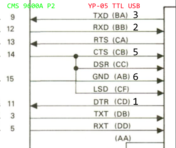
|
PHEW!
Sunday, January 3, 2021
MIKUL 6218 Memory and VIA EXORbus board
I haven't spent much time working on my CMS 9639 SBC because, unlike the CMS 9619, it does not have any usable on-board RAM and does not include a monitor/debugger in ROM. Instead, it is designed to use an external memory board (which I don't have) on a back plane (which I now have) and boot OS-9 from a disk drive (which I don't have). What is nice about the device is the built-in memory manager which uses up to 1MiB of RAM. Unfortunately, EXORbus RAM cards are still prohibitively expensive on eBay and only have 16K to 64K of RAM capacity. Since the components would be far less than the price of those boards, I took a stab at designing a 1MiB SRAM board with a bonus additional I/O expansion.
I had just started to get components inserted into an EXORbus prototype board when I noticed the MIKUL 6218 Memory and VIA boards appearing on eBay at reasonable prices (<$45 shipped). Let's take a look at the board:

Click below for more details...
Subscribe to:
Posts (Atom)