Tuesday, March 26, 2019

Solder On! and KIM-2e Addressing

I wish I had fun things to report, but I am just doing tons of point to point soldering on the SUPERPROTO card, and the Keypad/LED main board.

Keypad/LED main board

In the meantime, I can describe some of the theory behind how the KIM-IIe card should work (click below to see the gorey details).

Friday, March 15, 2019

KIM-2e Half Time Update

Here is the halftime status for my RetroChallenge 2019/03 project "KIM-2e" a KIM-1 simulator for the Apple //e . To review, I am using Mike Willegal's SUPERPROTO card as a foundation for my project. I am adapting it to use the MOS 6532 RIOT, rather than the MOS 6522 VIA. I don't have a GAL programmer, so I am using my own logic (basically from the KIM-1 schematic) to decode everything. The system will use the Apple //e's inhibit function to keep the Apple's RAM off the data bus at the location the KIM-1 would expect to find the 6532. I am also building a keypad and display that is functionally the same as the KIM-1's. Of course, this is all just an exercise in entertainment since the Apple //e already has an excellent keyboard and display, and an easy to use system monitor. But the end result should be an Apple II that can run binaries for the KIM-1, unaltered and in their full glory. So, I will finally get to use my Apple //e to play Farmer Brown on a 7 segment LED display as it was intended!

It took a while to get my LED modules assembled. I ran into a few problems with the new pinout. mostly, the transistor legs are so skinny that they fall right out of the sockets if a resistor leg is in there. The jumpers helped wedge them in the socket, but order of operations was important, and the jumpers had to go in last. Here is my display BusBoard assembled, with most of the soldering complete.
On the main peripheral card, the adapter board for the MOS 6532 is complete, and hopefully functional. Some of the ICs are installed and wired up. I still need to add some more glue logic ICs and the header to connect to the keypad. I do not think I will have time to deal with the ROM. Instead I will just load the KIM-1 ROM into the Apple II RAM at the correct address.
I still have a lot of wiring to do here! I had a new idea on how to do some of the address decoding for a little more granularity, so there are some jumpers that I am in the process of moving. It is getting messy! On retrospect, the ICs could have been laid out a little differently for shorter address lines.

And finally, here is the mock-up of how the interface will look with the keypad and display board in the bottom half of the enclosure. Next, I need to solder in the header for the connector to the peripheral card and the socket for the display board, and add the decoder and buffer ICs on the bottom proto-board.

I will likely post a schematic of everything at the end of the month, but it is still undergoing so many changes as I go that I don't want to post anything yet. In the meantime, you can follow my status on this project at my RetroChallenge_2019/03 blog pages.

Tuesday, March 12, 2019

LED Module Mayhem

New Module Diagram

I had some time to test out my LED modules, only to discover that the pinout I used was not correct. I assumed the common anode was on pins 1 and 6 based on some spec sheets I found. This made it convenient to wire up as a module since there is an anode close to the top to connect with the transistor leg. Unfortunately, I discovered that the actual pinout has the common anode on pins 3 and 8 (see diagram). As a result, I have to rebuild all of my modules with new sockets, and figure out a way to run a jumper to the middle of the LED without interfering with the adjacent modules.

I also made a diagram of how the modules will connect to the back of the BusBoard. I always get confused soldering everything backwards unless I have a diagram. Unfortunately, after I had already cut a few of the traces, I realized that I put VCC (+5V power) on pin 1 instead of pin 16 where it usually is. I guess that is not too big of a deal though, so I am just keeping it as-is. The current-limiting resistors from the buffer start from under the adjacent LED so I have room for them to lay down on the board.

LED Board Diagram
Black = male header on the copper side;
Grey = LED module / socket on the board side;
Yellow = jumpers; Red = cut traces

Finally, I just received some 6x8mm proto-boards to be the main board for the LED BusBoard and the keyboard to mount on. They fit nicely into a Serpac handheld enclosure that I found a while back at my local electronics surplus store.

Monday, March 11, 2019

Adapter Armageddon

I finished soldering up my adapter board this weekend and cut off 2 unused rows to save space, but quickly realized that I need to make some changes. The SuperProto card routes the 6522's positive chip enable (CE) signal directly to VCC to always keep it active. I need to fix this because this signal needs to be controlled by my own logic. The negative chip enable (CE) is connected to DEV_SEL on the Apple II bus. This also has to be fixed as it will be connected to the Kim-1's K5 signal from the address decoder. I didn't handle these properly in the adapter and just connected them to the corresponding signal from the SuperProto card. I can either cut the lines on the card, or change the adapter card. I modified the adapter card and updated the diagram.

I also spent some time soldering in sockets for the ICs and connecting the address lines to the decoder ICs. I am running a lot more wires than I expected!

Thursday, March 7, 2019

LED Displays - Makin' Modules

The common anode 7 segment LEDs arrived from China yesterday, so I started assembling some modules that include the resistors and transistor necessary for each display. My plan is to mount these on a zig-zag Busboard to easily connect all of the pins for each segment, without a bunch of jumper wires.

My LEDs are smaller than the originals with a different pinout. Since I can't find the exact data sheet for them online, I need to do some experimentation before I solder anything in. As I was working, I noticed 5 pins of the modules that should not be connected to the bus. Rather than cut traces between each module, I just broke the legs off of the sockets. I can use those bus lines to carry the signals that select each display, instead.

Tuesday, March 5, 2019

KIM-2e MOS 6530 - 6532 - 6522 plan of attack

My SuperProto card arrived this weekend from the Russian Federation. I plan to modify it for the foundation of my KIM-2e card. The SuperProto is designed to use the MOS 6522 VIA and a separate ROM. The KIM-1 has MOS 6530 RRIOT ICs with integrated mask ROM. Since these are no longer available, several KIM-1 enthusiasts have replaced it with a MOS 6532 RIOT and separate ROM chip. The 6532 RIOT has a pinout that is fairly similar to the 6522 VIA. So, by switching some pins around, I can get a 6532 functioning on the SuperProto card, which already has a spot for the ROM chip.

Rather than cut up the beautiful SuperProto card, I am working on an adapter that will plug into the 40 pin socket on the card. Fortunately, it really doesn't matter how the pins are ordered on one side of the adapter since they just hook up to the prototyping area on the card, and I can connect to them however I want there. I started with a standard Radio Shack style multipurpose PCB and added male to male Round PCB pin headers. The pins are thinner than standard headers, so that they do not damage the chip socket on the main card. It was difficult to solder these on the copper side of the board. My first attempt left me with bridged pins which I struggled to fix with solder braid, and I ended up melting the plastic. It was just too hard to get the soldering iron and solder under the plastic while regulating the amount of solder going in. Then I realized I had put the long header on the wrong side of the board and had to start over anyway, ugh... I took some time to diagram out the copper side of the board so that I knew exactly where everything had to go. I had better luck pre-tinning the PCB holes and then hitting each pin base with the iron with a bit of solder on the tip. Gravity pulled the solder down to the pin, and I had good control of how much solder was going in.
pre-tinned holes

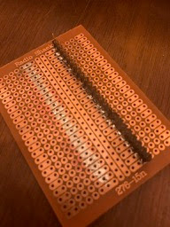
I pushed the tips of the socket legs to the left or right to bridge the gap to the next hole, depending on whether I wanted a connection to the headers, or not. The adapter is almost done, but it sits too low on the card for my taste. I probably should have swapped the locations of the socket and headers, but the address lines would have been difficult to re-route. I will probably need to cut the edge off the adapter to clear the mother board of the Apple IIe. Anyway, making progress...
half completed adapter

I also took a few minutes to test out the keypad and re-route a few traces. I caught a missed connection, and managed to eliminate a long jumper that I did not like. So, way too much soldering so far, and much more to come.
updated keypad

Sunday, March 3, 2019

Keypad Chaos

Since I didn't think I would have time to build the keypad or display, obviously I had to spend the weekend making a keypad. The SuperProto card I ordered from the Russian Federation hadn't arrived by Friday, so I thought this would be an easy start to the month. The layout is a bit strange (3x7 matrix, arranged as 4x5, plus the RS and ST keys) , so a normal keypad matrix won't work. I used the newer Kim-1 key layout with the SST switch on the left, and retained the same header pinout, so it should theoretically plug right into a KIM-1.


Of course, it took forever to route all of the wires by trial and error. Anyway, it's done (other than the step buttons), and it seems like it will work... but I need to get some decals so I know what key I am typing!

...and the SuperProto card finally arrived this weekend, just in time!