Thursday, April 23, 2020

OS9 shell on a real CMS 9619!

I finally got it working thanks to the advice of a kind member of the Tandy Color Computer (CoCo) discord channel. Interrupts! Once I connected the 6551 ACIA's IRQ line to the 6809's IRQ (using the CMS 9619's TS8 jumper block), the OS9 shell came alive:

You can see the system start up with the ROM's "DEBUG19" prompt. Then it proceeds to:

  1. clear some memory
  2. use the edit memory command to enter in the ZMODEM program and a mini boot-loader
  3. jump to the boot-loader to get the first part of the kernel into memory sector by sector from a disk image
  4. jump to the NitrOS9 Kernel.
  5. The kernel starts loading in more sectors using its ZMODEM boot module, until it finally runs the terminal shell and gives me an "OS9:" prompt.

And now, with interrupts enabled, the shell responds! Now I need a proper ZMODEM file manager to load in and run other programs.

Tuesday, April 21, 2020

Fortunately... Unfortunately...

While I was waiting for my RAM to arrived, I tried burning an EEPROM for NitrOS-9 so that I could make the load time shorter and avoid the relocation problems I thought I was having. Well, it did not work.
Filled up Sockets! This would have cost
many hundreds of dollars back in the day.
Fortunately, my SRAM chips arrived early, so I got to work on installing them. Since the board expects EPROMS where I am putting the SRAM, I had to remove some jumpers that disabled writing to the sockets. I felt bad removing the beautifully wire-wrapped jumpers and replacing them with plastic jumpers, but it is for a good cause. With writing to the SRAM enabled, I tried booting. I thought it worked perfectly at first, but I realized I had run my expect script for the emulator instead of the real board. When I ran the correct script, I was sorely disappointed to find that everything was getting stuck just before the kernel was supposed to get loaded. After a lot of debugging, I figured out the problem. I had padded out the boot modules to align with the beginning of memory pages so that everything was easy to debug and compare to the source listings. Unfortunately, the emulated MC6809 was much more tolerant of scanning past the fill characters than the real MC6809. Once I got rid of the padding, everything started working... to a point. Where I was supposed to be greeted with the NitrOS-9 startup screen, I was getting gibberish:

Fortunately, this particular type of gibberish is recognizable as a baud rate mismatch, which makes sense. NitrOS-9 uses a completely different system for getting the baud rate than the CMS 9619 uses. After an adjustment to the terminal description files, I had an improvement:

YES! I was so excited until I hit the return key and... nothing. It does not respond with another prompt or an error or anything. Just stuck. More work to do...


Saturday, April 18, 2020

Interru(o)ptions

This post is just to document and explore some of the interrupt options on the CMS 9619 that could be compatible with NitrOS-9's interrupt requirements (60Hz based on VSYNC).

RTC-58323 Real Time Clock

The CMS 9619's RTC can output a standard clock signal. The CMS 9619 has jumper block (TS10) that allows you to select a signal to connect to the Control B input (CB1) on PIA0. The signals are:

  • 1 hour
  • 1 minute
  • 1 second
  • 1024 Hz

1024Hz seems too fast and 1Hz is too slow for the interrupt we need. But, it's nice to know it is there. Probably better for a watchdog timer.

MC6840 Programmable Timer Module

The MC6840 timer in the CMS 9619 can generate a continuous square wave from 1MHz (1/2 the system clock speed) to about 141 years. The MC6840 can generate an interrupt every low transition of the output, or any of outputs can be jumped to the Control A input (CA1) on PIA0 using the CMS 9619's TS14 jumper block. I am not sure why there are 2 options to generate the interrupt here though.

To get an approximately 60Hz signal, I need to configure the MC6840 with a $4000 (16,382) divider of the system clock (1/((16,382+1)(2E-6)*2) = 61.03Hz). This should be easy to configure in the MC6840 16-bit Continuous Operating Mode.

Using the MC6840 PTM with a jumper wire to the right side of the TS10 jumper block (at the RTC), which connects to the MC6821 PIA's CB1 seems like the most suitable choice. It is almost identical to NitrOS-9's standard VSYNC interrupt on the CoCo's PIAO CB1 so I can re-use most of the code, and seems highly configurable.

External Circuit

The MC6840 Application Guide contains a circuit for getting a 60Hz TTL signal from the 120V power lines. I think this signal could work as a trigger to the MC6840 or the MC6821 PIA. However, it is overly complicated for this project, which does not need exact long-term timing.

Aside

I spent some time watching the "Virtual" CoCoFEST for inspiration today. Check it out!

Friday, April 17, 2020

Kernel of Truth

I spent some time today trying to get NitrOS-9 booting on the CMS 9619 SBC. I was able to get this working in emulation, so I was hopeful that it would be an easy job with real hardware. After some minor modifications to deal with timing in the slower environment, the ZMODEM module is working perfectly! However, getting NitrOS-9 running has been much more complicated.

As part of the boot process, NitrOS-9 relocates the kernel "disk" sectors from $2600 to high memory. Memory was cheap with my 6809 emulator, so everything that is not ROM was configured as RAM. The emulator easily relocated the kernel to $C000-$Dxxx, just below the main debug ROM at $E000-$FFFF. On my real board, that address range is not populated with RAM, so, I was relocating the kernel into thin air! I changed the load area to $7000-$8xxx, but had a problem because the relocation routines expect the video buffer at $8000, and over-write part of the kernel. I could keep toying with the relocation routines, but I think I just need to get more SRAM to populate the empty ROM sockets. I just put an order in, and am hoping for for some new 8K SRAM ICs by the end of next week.

Thursday, April 9, 2020

CMS 9619 Hardware Mods

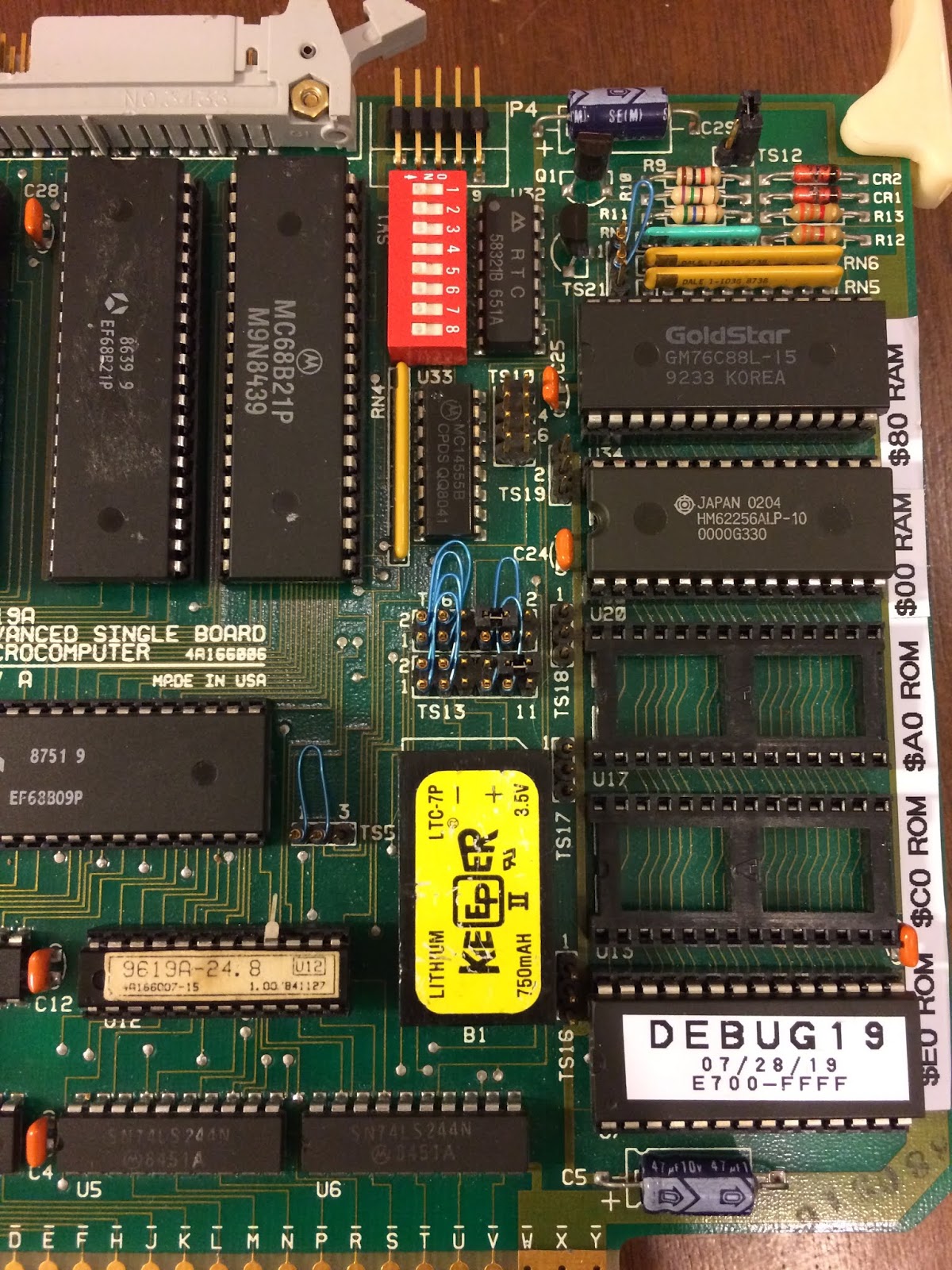
Note the 5 28 pin sockets on the right side of
the board for 4K or 8K SRAM or ROMs

In order to get NitrOS-9 running on my CMS 9619 SBC, I am going to need a lot more RAM. This board is configured to have up to 8K of onboard RAM and 32K of onboard EPROM, with options to use 4K or 8K chips. 32K and 64K RAM expansion boards were available in several configurations, including battery powered non-volatile SRAM to retain state during power off. Unfortunately I haven’t seen any of these available at a decent price, so expansion boards are not a good option for me. I do have a 32K SRAM chip with a similar pin-out (part of an eBay Dragon 32 IC kit) to the 8K module which would fit nicely.

My board already has 8K of RAM installed in socket U34 ($8000-$9FFF), and 8K of ROM in socket U7 ($E000-$FFFF). Socket U20 is not selected by the PAL decoder on this particular board, either by design (being configured for 1 x 8K DIP SRAM vs. 2 x 4K SRAM) or due to some problem with the PAL. My new 32K SRAM needs to be selected and addressed, which requires some minor modifications to the board.

To select the new 32K RAM chip, I first raised pin 16 of the PAL decoder IC normally responsible for enabling the U20 RAM socket (apparently not working on my board). Once that was done, I used the A15 address signal to enable U20 socket instead. This required a short jumper wire from pin 3 (A15) to pin 16 (U20 CS') across the PAL address decoder. So now, whenever the A15 line is low ($0000-$7FFF), the SRAM in U20 will be enabled. This is perfect since the SRAM IC is 32K, and will fill the bottom half of the board's address space.

To address all 32K of the SRAM, I first cut the GND signal from pin 1 of the U20 socket. This is tricky since the trace is right against the socket. I ran a jumper from pin 5 of the PAL decoder to pin 1 of the U20 socket (A14). Then I set the jumper at TS19 to connect pins 2 and 3 (A13), and the jumper at TS6 to connect 8 and 10 (A11). Socket U20 now has the address lines it needs to decode all 32K of memory.

Two long jumpers to connect A13 (I realized later this is handled by jumper TS19) and A14,
and one short jumper for A15

I was hopeful that everything would just work with the modifications, but of course it wasn’t that easy. The problem has to do with the data bus transceiver (U11) on the board. It is driving “data” from the EXORbus onto the processor data bus in the address range of the new RAM. However, there isn’t anything on the bus to drive and it is just causing contention with the new SRAM. For now, I disabled the transceiver by disconnecting the dead-bug'ed delay line from the enable pin (pin 19) of the transceiver, and pulled that enable pin high with a short jumper wire to Vcc. This isn’t ideal because it disables all of the external bus, including the I/O address range in addition to the low memory range that we need. So right now the CMS 9619 can’t read anything else on the EXORbus.


Short jumper to disable the EXORbus data bus transceiver (U11)

So, with 40K of RAM (8K in U and 32K in U20), and 8K of ROM with sockets for another another 16K, the board is nicely outfitted to run some real programs.

Tuesday, April 7, 2020

RetroChallenge 2020/04 is here!

I'm starting a bit late, but since I am in quarantine and working on some old computer stuff anyway, why not enter?! Here are my goals for RetroChallenge 2020/04: