With the the power and serial port breakout boards hooked up, I tried turning on the CMS 9619, with no luck- nothing from the serial ports. The ROM I received with the unit is set up to run some user code on the second ROM at start-up, skipping the debugger. So, I made a patch to the ROM to make sure that the reset vector points to the debugger init code. The update has now been committed to the CMS_SBC GitHub code archive.
Unfortunately, this 2 byte change took several hours to get into an EEPROM, since I only have my Apple IIe and a Super Serial Card (SSC) to use as an EEPROM programmer. I had to make some changes to the BASIC EEPROM programmer script (Read More to see the program). I modified it so that it allows me time to switch in each 2K bank of the 8K EEPROM. Then I made the mistake of trying to upload the hex dump using a terminal connection to the Apple IIe (using another SSC with the standard ROM). Even at 19.2K bps, it took over an hour due to an overly conservative text pacing setting. I'm not sure why it took so long, but, of course, I soon realized that I had forgotten to move the jumpers to allow the programmer SSC to write to the EEPROM. The jumpers where located under my bank-switching adapter board, so I had to shut everything down to reach them. Then I discovered an off-by-one error in the BASIC code and had to start the upload over. Switching to the method I previously described by using c2t to encode the ROM hex dump, then using the Apple //e's cassette input port made things go MUCH faster.

After installing the new ROM and powering on the CMS SBC, I still did not get anything from the serial ports. Some voltage testing led me to discover that the +12V was not making it to the RS232 receivers. I had hooked up the power to an ambiguously marked (and fortunately unused) pin 'U' rather than pin 'T' on the extension board.
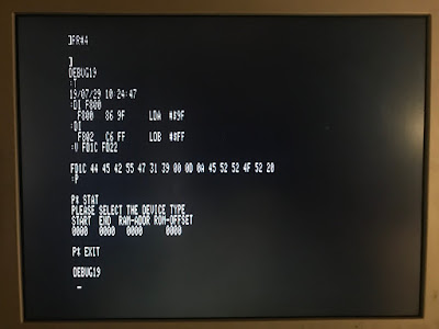
With power now going to all the right places, I was shocked to be greeted by:
DEBUG19
:
It worked! But it did not seem to be accepting any input. As it turns out, my wiring to the serial port adapter was slightly wrong in implementing a cross-over cable. After referring to a nice diagram online, and moving my Carrier Detect lines, it started accepting input!

Here are some of the commands I had a chance to disassemble and use ("H" is a hex digit):
- R - Display the 6809 registers.
- P - Enter the EPROM programmer.
- STAT for status.
- EXIT to quit.
- T - Show the time from the RTC.
- S - Set the time for the RTC. Format: "S YYMMDD HHMMSS"
- E - Edit Memory. Format: "E HHHH"
- Responds with "HHHH HH"
- Enter: "HH" to set the hex value in memory.
- [space key] for next byte.
- "-" to go back a byte.
- V - View Memory. Format: "V HHHH HHHH"
- M - Move Memory. Format: "M HHHH HHHH HHHH", Source, Destination, Length.
- G - Go to Memory (run). "G HHHH"
- C - Clear Memory. Format: "C HHHH HHHH"
- DI - Disassemble Instruction. Format: "DI HHHH", subsequent DI disassembles next address.
- DB - Disassemble Block. Subsequent DB disassembles next block.
I very happy that this finally worked. It goes to show how useful an old Apple II is: I used a Centronics printer card to figure out the scheme of the PAL address decoder, a Super Serial Card to download the EPROMs and program the EEPROMs, and settled on the cassette input port to upload data. Now, to figure out something useful to do with the MC6809 SBC!
Check out all of the related blog posts for more details.

