Showing posts with label RS232. Show all posts

Thursday, June 30, 2022

Synertek MBC020 Serial Snags

Serial Cable

I spent a few minutes continuity testing the P3 card edge connector for the serial port so that I could build a serial cable for the MBC020. I was hopeful that this was just a 1:1 pinout for a card edge to DB-25 RS-232 IDC connector, like one I built for my Motorola MC68000 Educational Computer Board. It is almost exactly right except the send (TxD) and receive (RxD) data lines are swapped. I thought maybe it was wired as a DCE device, but in fact, only the data lines are switched. As annoying as this was, it wasn't too difficult to put a twist in part of the ribbon cable, swapping wires 3 and 5:

Card Edge to DB25 serial cable

Note the twist in the green, yellow, and orange wires near the DB25 connector on the bottom right of the picture.

Serial Output

With the serial cable constructed and a null modem adapter attached, it was time to power it up! I installed the card in my EXORbus "MULTI-PLANE" backplane, and booted it up. Unfortunately, no matter what baud rate I tried, I was only receiving data that looked like a baud rate mismatch. I double checked the MBC020 driver source code in mame to see if it provided any hints, and sure enough, it apparently set 9600 baud, 7 data bits with 2 start bits. This effectively eliminates a high bit 7, as you would also need in the Apple II monitor. However, after apparently configuring GNU screen, it still did not work. Examining a hex dump of the output showed: 00000000: 00d3 c5d2 d6cf cdcf cea0 d6c5 d2a0 b4ae ................ 00000010: b08d 8ac3 cfd0 d9d2 c9c7 c8d4 a0ca d5cc ................ 00000020: adb1 b9b8 b3a0 d4cf d2d1 d5c5 a0d3 d9d3 ................ 00000030: d4c5 cdd3 a0c9 cec3 ae8d 8abe c800 ..............

This appeared to be the data I wanted, but bit 7 was still set high, making the text unreadable. After a quick check of my screen command line parameters, I realized that screen expects the serial options to be comma separated. Duh! The command:
screen -L /dev/cu.usbserial 9600,cs7,cstopb
did the trick perfectly and allowed me to finally interact with the real SERVOMON monitor:
SERVOMON VER 4.0 COPYRIGHT JUL-1983 TORQUE SYSTEMS INC. >V 0000-000F 0000 BF BF 9F BF BF BF 9F BF,B8 0008 9F AF BF BF BF BF BF BF,80 0B80 >F 00,0000-00F >V 0000-000F 0000 00 00 00 00 00 00 00 00,00 0008 00 00 00 00 00 00 00 00,00 0000 >J 1 MPC DIGITAL DRIVE REV 4.0 JUL-1983. AXES FOUND ON-LINE : 4 Ok AUTO ER 00 >G SERVOMON VER 4.0 COPYRIGHT JUL-1983 TORQUE SYSTEMS INC. >

Success! Next I will test out composite video output! Special thanks to "andysa" on the 6502.org Forum for sharing his notes on this board with me.

Monday, July 29, 2019

CMS 9619 SUCCESS!

With the the power and serial port breakout boards hooked up, I tried turning on the CMS 9619, with no luck- nothing from the serial ports. The ROM I received with the unit is set up to run some user code on the second ROM at start-up, skipping the debugger. So, I made a patch to the ROM to make sure that the reset vector points to the debugger init code. The update has now been committed to the CMS_SBC GitHub code archive.

Unfortunately, this 2 byte change took several hours to get into an EEPROM, since I only have my Apple IIe and a Super Serial Card (SSC) to use as an EEPROM programmer. I had to make some changes to the BASIC EEPROM programmer script (Read More to see the program). I modified it so that it allows me time to switch in each 2K bank of the 8K EEPROM. Then I made the mistake of trying to upload the hex dump using a terminal connection to the Apple IIe (using another SSC with the standard ROM). Even at 19.2K bps, it took over an hour due to an overly conservative text pacing setting. I'm not sure why it took so long, but, of course, I soon realized that I had forgotten to move the jumpers to allow the programmer SSC to write to the EEPROM. The jumpers where located under my bank-switching adapter board, so I had to shut everything down to reach them. Then I discovered an off-by-one error in the BASIC code and had to start the upload over. Switching to the method I previously described by using c2t to encode the ROM hex dump, then using the Apple //e's cassette input port made things go MUCH faster.

Slow serial upload to Apple IIe System Monitor

After installing the new ROM and powering on the CMS SBC, I still did not get anything from the serial ports. Some voltage testing led me to discover that the +12V was not making it to the RS232 receivers. I had hooked up the power to an ambiguously marked (and fortunately unused) pin 'U' rather than pin 'T' on the extension board.
With power now going to all the right places, I was shocked to be greeted by:
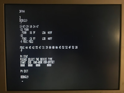
DEBUG19 :
It worked! But it did not seem to be accepting any input. As it turns out, my wiring to the serial port adapter was slightly wrong in implementing a cross-over cable. After referring to a nice diagram online, and moving my Carrier Detect lines, it started accepting input!
APPLE IIe terminal connection to CMS 9619

Here are some of the commands I had a chance to disassemble and use ("H" is a hex digit):

  • R - Display the 6809 registers.
  • P - Enter the EPROM programmer.
    • STAT for status.
    • EXIT to quit.
  • T - Show the time from the RTC.
  • S - Set the time for the RTC. Format: "S YYMMDD HHMMSS"
  • E - Edit Memory. Format: "E HHHH"
    • Responds with "HHHH HH"
    • Enter: "HH" to set the hex value in memory.
    • [space key] for next byte.
    • "-" to go back a byte.
  • V - View Memory. Format: "V HHHH HHHH"
  • M - Move Memory. Format: "M HHHH HHHH HHHH", Source, Destination, Length.
  • G - Go to Memory (run). "G HHHH"
  • C - Clear Memory. Format: "C HHHH HHHH"
  • DI - Disassemble Instruction. Format: "DI HHHH", subsequent DI disassembles next address.
  • DB - Disassemble Block. Subsequent DB disassembles next block.

I very happy that this finally worked. It goes to show how useful an old Apple II is: I used a Centronics printer card to figure out the scheme of the PAL address decoder, a Super Serial Card to download the EPROMs and program the EEPROMs, and settled on the cassette input port to upload data. Now, to figure out something useful to do with the MC6809 SBC!

Check out all of the related blog posts for more details.

Sunday, July 21, 2019

CMS 9619 SBC Power and Serial Ports

Power

I don't have a proper card cage for a micromodule system, and clipping power leads to the card edge seemed a little sketchy, so I created a power supply connection to the CMS SBC board using:

  • CMS 9630 EXTENDER board (came with the 9619)
  • ATX power supply (had it in my parts bin)
  • ATX breakout board ($5-10 on ebay)
  • wires, test clips, and terminals (~$5 from my local surplus store)

After everything is connected up, here it what it looks like:
ATX breakout, extender board, and CMS 9619 SBC

This is probably overkill as the only thing that uses the ±12V are the RS232 transceivers which would probably run fine with ±5V

Serial Ports

After struggling with how to get standard DB9 serial ports from the randomly placed signals in the CMS SBC's 26 pin header, I decided to build a small breakout board ("BOB") to handle the conversion. It has: 26 pin IDC -> BOB -> dual DB9 IDC connectors. Then I did all of the wiring re-organization on the BOB with some point-to-point soldering. 26 pin P2 to DB9 adapter board

Sunday, January 31, 2016

Truly Wireless Now

In a quest to make my Apple //e truly wireless, I did some soldering this morning to create a cable to go directly from the Apple Super Serial Card to the USR-WIFI232. This allowed me to get rid of the bulky DB-25->DB-9 adapter, and a short DB-9 cable to go from the adapter to the USR-WIFI232 (see photos).  Then, I used double-stick tape to mount the USR-WIFI232 on top of the Apple //e power supply. The Apple //e already has a pop-out that fits the antenna and power supply cord fairly well. The result is an internal WIFI adapter! I suppose I could get the power for the adapter from the Apple power supply, but I'd rather not run the risk.

I really like this set-up as connecting to the Apple over serial cables always meant finding the right cables and adapters, or a null modem. They would inevitably get unplugged for another project or to move the computer.

There is a lot of potential for this configuration for transferring disk images with ADTPro. I have to use 300 baud for the Apple BASIC interpreter to keep up, but it looks like higher baud rates will work in the terminal mode of the SSC, or with a compiled program. Come to think of it, you could even have a web page on the Apple //e that accepted disk image uploads.

This is a simple, and inexpensive ($40 on ebay) alternative to some of the other Apple Ethernet products out there. Some people have done similar things with a Raspberry Pi, but, again, this is pretty much plug and play and includes WIFI.

Having made two web servers out of old Apples, I am finding that it would be a lot more interesting to make a web browser. That will probably be a future project.

Wednesday, January 27, 2016

WIFI enabled!

I took the day off from work, so I had a chance to get some real RetroChallenge work done!

It took a while to figure out that the USR-WIFI232 needs a null modem adapter to connect to a normal computer (but not to the Apple IIe in Terminal mode). I did not see that documented anywhere. Once I figured that out, I played around with the converter on my MacBook and my good ol' Macintosh G3. Some well-hidden tips:

  1. Use a null modem to connect
  2. type +++ to set the terminal mode. the module will respond with a
  3. type a and the module responds with +ok
  4. type AT+H for a list of commands.

I have struggled for a while to get my Apple IIe to connect to anything but my Macintosh G3, running ZTerm. This problem was apparent when I was unable to communicate between my Apple IIe and the USR-WIFI232 device. Oddly, I noticed that anything I typed was being echoed by the USR-WIFI232, but it would not respond to the Apple IIe. In fact, I was able to connect my Apple IIe, the G3 and the USR-WIFI232, at the same time, and view a complete transaction between the G3 and the USR-WIFI232 from the Apple IIe, but it would still not communicate with the USR-WIFI232!

I played around with the settings and discovered that the problem is that the (just mine?) Apple IIe Super Serial Card (SSC) does not seem to communicate correctly in the 8 Data, 1 Stop, 0 Parity mode. I had enabled the "No Extended Characters (strip hi bit)" setting in ZTerm which fixed the problem, but only for ZTerm. I think the Apple IIe was sending data with the high-bit enabled, which being echoed by the USR-WIFI232, then the Apple IIe would strip the high-bit making it look OK, even though the characters were junk.

Anyway, 7 Data, 1 Stop, 0 Parity mode works correctly. So, to enable this setting on the Apple IIe, enter <ctrl-A> and then at the APPLE SSC: prompt, enter: 1D . For the USR-WIFI232, enter: AT+UART=9600,7,1,None,NFC, then AT+Z. Once I did that, I was able to send and receive commands between the Apple IIe and the USR-WIFI232! I am losing a little bit of data from the USR-WIFI232 at speeds greater than 300 Baud though.

Using the Terminal mode of the SSC, I could send various AT commands to the USR-WIFI232, but I couldn't really do much with it other than PING or scan for WIFI networks. Then, I discovered the built-in web socket webpage. This allowed me to send data through the webpage to the Apple IIe! When I exited the SSC terminal mode, I could send commands to AppleSoft BASIC, and I even ran a little program.

Friday, January 9, 2015

Debugging the Debugging

I have been working on a way to get the proper debug logs out of ElWhip without using the modal dialog boxes which cause the program to stall until a user presses the 'OK' button. I have decided to just dump the logging output through the printer port, since I already have serial port code for ppp and the modem port. Unfortunately, that means I would need another serial connection between the Macintoshes. But, feeling inspired by another Retrochallenge project, I set up a bluetooth rs232 adapter for a wireless connection. I initially had a problem where bringing up the serial connection to the printer port would bring down the connection to the modem port, but I worked through a couple of bugs to get it working.

This should make it much easier to troubleshoot some of the intermittent problems I have had establishing the ppp connection and retrieving the web page.

 Wireless Logging with Bolutek RS232 - Bluetooth Adapter 

Saturday, June 21, 2014

Spending Spree, part 2

Earlier this year, I took a chance on buying one of these poorly documented Chinese BOLUTEK RS232 / Bluetooth modules. I followed these instructions, and to my surprise, it worked great for a basic wireless serial terminal between my G4 (with USB Bluetooth adapter) and Mac SE. Hopefully, I can use it to establish a wireless PPP link to my Macintosh 128k. First, I need to re-solder my broken RS422 to RS232 adapter, though. Wireless internet, here I come!

Oh, and the Fanny Mac arrived already. It fits and works great!

Tuesday, December 31, 2013

Setting Up the Work Environment

I couldn't wait any longer! I dusted off my Macs and booted them all up to make sure I wouldn't spend the whole month fixing hardware. They all work!

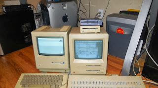
Mac G4, 128K, SE

Hardware

Basically, I will be using a PowerMac G4 to do the software development and the Macintosh SE for initial testing. I decided to do testing on the Mac SE for a few reasons:

  • faster serial ports for data transfer;
  • ethernet card installed (broken?);
  • MacTCP and FreePPP installed for comparison testing;
  • SCSI port and a harddrive;
  • more robust System software (System 7.1);
  • same Motorola 68k processor as the 128K.
This should make testing much less painful. If I get anything working on the SE, I can give it a try on the Mac 128K. I have an external SCSI zip drive that seems to work well as an external harddrive (and lots of zip disks!).

Wednesday, December 4, 2013

RetroChallenge 2014WW Entry

I have again entered the RetroChallenge! This time I will be using my Apple Power Macintosh G4 500 DP from the year 2000 to compile some programs. Now, even though this computer is technically eligible for the RetroChallenge, the real "retro" part is that the program I will be compiling is for the Apple Macintosh, as in, the original 128K Macintosh from 1984. I will be using the Classic Environment of Mac OS X 10.4 running MPW as my development environment.

As for the programming, I will attempt to port the lwIP TCP/IP stack to the original Macintosh. This Macintosh is unique because it did not have enough memory to run any commercially available networking stack. Even the 512K Macintosh had some networking possibilities. I attempted this project a number of years ago but couldn't get past the multi-thread requirement of the lwip PPP implementation. As far as I know, the original Macintosh operating system does not have any multithreading libraries or routines. I recently noticed that a branch of the lwIP code includes a PPP module that claims to not require multiple threads! So I will give this another shot. If PPP fails, I can try to get SLIP working instead.

Here is my target hardware/software flow:

Macintosh -> lwIP -> ppp ->  RS-422 -> RS-232 -> USB -> PowerMac G4 -> getty -> pppd -> THE WORLD!

Having worked on this before, and having struggled to understand how to use the code, I have a feeling I will get stuck at some point. If that happens, I will probably work on building a ROM burner to flash some Apple II ROMS or work in my Apple IIgs.

Monday, July 26, 2010

RetroChallenge cables

I am going to need 3 different types of cables to hook up to my future router:

  • DB9 RS422 (old classic Macs)
  • mini-DIN8 RS422 (newer classic Macs)
  • DB9 RS232 (new usb to serial converter)

The 3com documentation for a similar router has all of the pin-outs. The router uses an connector RJ-45 for the AUX serial and console ports, and a DB50(!) connector for the Serial port and the expansion card I bought.

So I went scavenging through the thrift store today to find some old serial cables. I found an old serial port adapter for a Parallel HP printer. It does not look like a real serial to parallel adapter (rather some printer-specific implementation), so I will be cutting off the nice mini-Din8 end of it to make a serial cable for my Mac SE or SE/30.

I bought some male DB9 to RJ45 modular adapters at the surplus electronics store earlier this month. I want to make sure that the pin-outs are correct on the router before I insert the pins in the adapters, because they are really hard to remove. This will connect to the 512K and 128K Macintoshes. I can just use a standard ethernet cable to connect to the router's AUX and console ports. Even though these Macs do not have TCP/IP, I hope the router has a telnet client built in. That will allow a normal serial terminal to connect to the router, then out to other machines.

The USB-serial adapter is easy, and only needs a straight through DB9 cable to connect to the AUX port adapter cable.

As for the DB50 connector, that is another story. I hope that it comes with an adapter cable!

RetroChallenge Part 2

Here is my router shipping info:
Status: In Transit - On Time  Scheduled Delivery Date: 07/30/2010
That gives me a full day to complete my experiment! With a list price of only $1,420.80, $25.00 is a pretty good deal. I paid $18.00 for the additional serial interface so I can hopefully have 6 ethernet-less Macs connected to the internet at once.

Saturday, July 24, 2010

RetroChallenge

With only one week to go, I decided to enter the RetroChallenge. The plan is to get all of my Ethernet-less Macs online without having to buy expensive hardware, and without using another computer. here is how I used to do it: Getting a Classic Mac online using a Mac OS X server. And here is what I want to try: 3com 5009 router. This is an high-end router that is readily available online for about $25 including shipping. It has 2 serial ports. The plan is to hook the Mac serial ports up to it and make the connection through PPP.