Lots of robot goodies arriving for Retrochallenge! It is taking all my willpower to not assemble that robot chassis...

Lots of robot goodies arriving for Retrochallenge! It is taking all my willpower to not assemble that robot chassis...
I was really inspired by avretro's MC14500b based RetroChallenge project a few years ago. A line following robot is such a perfect application for the 1-bit processor. I was so inspired that I think I will work on a similar project: a Halloween themed MC14000b based line following robot. Unlike avretro, I will try to stick to era-correct main components to get it working and hopefully keep it quite simple.
If I manage to complete that, I also want to get my recently acquired Motorola MicroModule O1A2 working with at least a debugger and figure out a serial connection to my Elenco 6802D5 (rebranded MEK6802D5).
 [Bing co-pilot is obviously unfamiliar with the data bus width of the MC14500b]
In the past I had a lot of difficulty finding a reasonably priced backplanes and card cages for EXORbus systems and ended up trying to make my own. Since then, I have discovered many more PLC manufacturers that made EXORbus based systems and have been able to find more reasonably priced processor cards, backplanes, and cages. As a result, I did not find it necessary to make a new run of my Multi-Plane ExorBus backplanes. Instead, I am going to finalize and open source the design so that others can have it manufactured if they want.

Almost a year ago, I saw a Semy Engineering cage and backplane on sale for about $150. They typically are listed for over $500, but like much of this EXORbus hardware, it sits for sale for a long time, awaiting the perfect buyer who has a malfunctioning PLC system and a silicon wafer production line waiting on it to get repaired. As more and more of it reaches end-of-life, it accumulates on ebay until there is a glut, and finally the prices are slashed. While the price still isn't cheap, it is probably a better deal than trying to make one myself... or so I thought.
Unfortunately, when it arrived, I realized that it did not have a ±12V power supply for the RS-232 line drivers on my boards, only the +5V main power supply. This probably isn't too big of a deal, as most modern equipment deals well with lower RS-232 voltages and I am not planning on running very long serial communication lines. However, I felt like it was worth the time to get this running the right way. So, the hunt for suitable power supplies began.
Searching for a ±12V PSU is pretty difficult, as there is not a widely used term to describe them, and the minus sign usually gets ignored by the search or acts as a NOT operator. "Dual rail" led me to some decent options, and the electronics parts suppler search filters were helpful to find some (expensive) power supplies too. The MEAN WELL PD-2512 is a well-priced option, but it is quite large, and I dont need nearly that much power.

Apparently, you can connect two 12V switch mode power supplies so that the negative wire of one is connected to the positive terminal of the other (creating a GND reference), and leaving you with +12V, GND, and -12V power. While I understand how you could do this with two transformers to effectively create a single center-tapped transformer, I am struggling to wrap my head around how this would work properly with the various diodes and voltage regulators that might be involved in the full power supply. I believe a single 24V power supply with a "virtual center tap" GND reference using a couple of resistors would work as well to give ±12V, rather than just +24V. I am not excited about either of these options and I am not willing to risk my boards if this does not work properly.
While attempting to solve the ±12V issue, I noticed that my Multi-Plane backplane fit perfectly into the card slot, as was intended (whew)! The Multi-Plane was designed to be an ATX power supply injector for another backplane just like this. However, when I designed the board there really wansn't enough space to include the ATX power connector in a location that would allow to clear the sides of a card cage and clear the cards inserted into the board at the same time. So, To get it to work in this cage, I would need to swap the right angle ATX PSU connector with a straight one (or cut a hole in the side of the cage), but then I would lose a slot, I would still need an external ATX power supply, and I would not be able to use the MULTI-PLANE for anything else. This really isn't a great solution for me, just to get ±12V power.
In the end, I stumbled across an "EVD/DVD Universal Switching Power Supply Module" that is very cheap (<$6 shipped), widely available, and provides the ±12V at a reasonable 200mA for each rail.

The DVD power supply has a 7 pin XH (2.54mm pitch) header for the output power and a 3 pin CH (3.96mm pitch) header for the AC input and another for the switch. I went ahead and bought a pre-made pigtail for the XH header ("JST XH 2.54 2~12 Pin Connector Plug Single Head With 300MM Wire") and rearranged the wires so that the voltages would correspond with the wire colors, just like an ATX power supply.
A used two of the existing holes in the case to mount a couple of nylon posts for the new power supply board. One required a new hole in power supply PCB but fortunately it landed on the ground plane. I glued two more nylon posts onto the case, aligned with existing holes in the power supply board. I rigged up a splitter/extension harness to give the board 120V AC power from the plug socket. I also needed to add a jumper wire for the switch socket so that it will remain powered on. This case does not have a power switch on it, but I expect to add one to a front panel once I get it built.
Next, I removed the backplane and soldered up the pigtail for the DVD power supply to the appropriate pins and ground plane. I also soldered up some wire to ensure that every slot gets the 12V power.

After a bit of testing to make sure the voltages looked correct, I plugged in an expendable board and was happy to see everything working!

Now I can start building up a usable OS-9 system that I won't have to tear-down every time I want to do some experiments with another board.
A while back, I tested out the video output on my new-to-me SYNERTEK MBC020 ExorBus SBC, and noticed problems with the upper half of the video. I wanted to make sure it was not my LCD monitor that was at issue so, I went out and bought a 9" black and white CRT security monitor to use for further testing. Unfortunately, when I recently went to connect it to the monitor, I could not get the MBC020 to boot anymore!
This is a good excuse to share some troubleshooting tips for these vintage SBCs.
With this procedure I was able to pretty quickly determine that I had no clock signal to the CPU. After I swapped a few ICs in the circuit around the oscillator with no improvement it became apparent that the crystal was likely at fault. This problem seemed consistent with my nearly 2-year-old son knocking the board off of the dining room table a few months ago. I ordered the crystal and that brings us to now, the first week of RetroChallenge.
Replacing the crystal was pretty straight-forward, despite the large amount of solder on the board in that area. I did have to use a small drill bit to completely clean out one of the vias, but no big deal. I really dreaded turning the board on for the first time though. If the problew was something other than the crystal, I would be very stumped and my RC2023/10 would get stalled right out of the gate.

Fortunately, everything came right back to life! The CRT monitor initially showed the same skewed image as the LCD, but after some heavy adjustment to the vertical hold, I ended up with a nice clear display. Although everything seemed to be working, I did notice some spurious "E" characters popping up after a command is completed. I am not sure if this is normal, or some new fault in the board, but I do not recall it happening before.

With everyting up and running, of course I had to mess with video connector and sudddenly I lost video and the terminal stopped responding. I tracked the problem down to a blown 5V fuse on the backplane. I must have short-circuited something. Fortunately, I still have a few hundred fuses left over from when I first built the backplane, so a new fuse and little soldering got it working again. I think I would definitely make the fuses easier to replace if I make another run of these backplanes.
This year for RetroChallenge, I think I will focus on some 6502 projects, mostly my Synertek MBC020 ExorBus board. I never got it working correcly as a terminal: skewed video and no keyboard yet. Let's see if I can get all of this working properly! This was supposed to be my project last year before I picked up a Radio Shack Micro Color Computer MC-10.

A while back I was fortunate enough to spot a CMS 9639A Memory Management Processor as part of a lot of boards in an eBay auction. This board sat on its box for a long while due to the extra cards I needed to interface with it. It does not have a debug ROM, no on-board system RAM, and the ROM is expecting a disk drive card (probably the CMS 9672 DMA Host Adapter) to actually boot from. At the time, I did not even have a proper backplane.
Since then, I built a backplane and re-purposed a relatively cheap MIKUL 6218 Memory and I/O card. After modifying the MIKUL card to have 1MiB of onboard RAM and reprogramming its address decoding to comply with the CMS 9639, I finally had something close to a usable system. Getting a disk drive working with the system was not something I was looking forward to. Fortunately, I had enough experience with NitrOS-9's 'DriveWire' disk emulation on my CMS 9619 port to know that it would be a good fit here too. Also, Søren Roug had done some great work disassmebling my CMS 9639's boot ROM and included it in his osnine-java project. This project includes lots of old Microware OS-9 source code from many systems. It has a very clever Java 6809 emulator that runs a native 6809 assembler to build all of the code.
First, I added the DriveWire module to the end of the boot ROM, in place of the normal disk drive boot module. After much experimentation, I was able to piece together a semi-working OS-9 system from the source code of other systems including the Dragon 128 and Positron 9000. Then, I struggled for quite a while as the computer did not seem to respond to my key input, even though it would send data to my terminal. Note that I had a similar problem with the CMS 9619 which came down to enabling interrupts. However, the CMS 9639 was designed to use OS-9, so it did not have interrupt enabling jumpers like the CMS 9619. I finally figured out that I had a flakey 6551 ACIA after swapping in a known good one. After using some of the NitrOS-9 tools to build a disk image, my CMS 9639 suddenly came to life! Some fine tuning of the modules and I was able to boot to the OS-9 shell and run some simple commands.
I stored all of my configuration to my fork of Søren's osnine-java repository.

| Left | Middle | Right |
|---|---|---|
| CMS 9600A MPU | CMS 9609 MPU | |
| CMS 9642 SERIAL I/O PROC. | ||
| CMS 9619A ASBM | CMS 9639A MMP |
I have seen a lot of overpowered PS/2 keyboard interfaces lately: microcontrollers, bit-banged PIAs, PIAs with shift registers. All sorts of complex solutions. Here is my simple contribution, using retro hardware.
It is important to note that the PS/2 protocol is basically just an isosynchronous serial connection with open-collector i/o. Isosynchronous is basically the same as the normal asynchronous serial connection, but there is also a clock signal. To simply implement this protocol, all we need is an ACIA or UART that supports a 1x clock mode and a buffer to make the signals open-collector. The 1x clock requirement rules out the common MOS 6551 (16X clock required), but includes many common alternatives such as the MC6850, Signetics 2651 and Zilog SIOs.
Next, the signals to the keyboard need to be buffered and converted to open-collector outputs. The 74LS05 open-collector hex inverter is a simple choice for this. Since this inverts the signals and the PS/2 data is already at the correct polarity, we need to invert the TX data signal 2x: invert the signal, pull it up, and invert it again. Here is an example for the MC6850:

Notice that the clock from the PS/2 device is connected to the ACIA as the RxClk, but is also inverted, pulled up and used as the ACIA TxClk. The RTS signal from the ACIA can be used to pull the PS/2 clock low for commands to the keyboard (untested). The data line from the PS/2 device is pulled up and connected directly to the ACIA, while the command data to the keyboard is inverted twice with open collector output.
If you only want to receive data from the keyboard, you can just connect up the clock (to ACIA RxClk) and the data line (to ACIA RxData) through non-inverting buffers (to protect the ACIA). Too simple!
Once you have the data from the ACIA, you will unfortunately need to use a small lookup table to translate the PS/2 keyboard codes to ASCII. A small PROM on the data lines of the ACIA could also work, but you would also need a tranceiver to do writes to the ACIA and a decoder to make sure the data moves through the PROM or tranceiver at the right times.
The one issue with this technique is that when using the 1x clock mode on the MC6850, I think that the the ACIA needs one more clock cycle than the PS/2 protocol provides per byte to indicate that there is a byte available (this could just be an issue with my clock phasing though). As a result, the input buffer full flag does not get set until the start of the next byte. Unfortunately, this means you are always one byte behind the keyboard. That may seem like a non-starter, but in reality, it does not affect much because the proper key code does get sent when the key is released. So every key press/release cycle sends you:
[previous key code]...[key code][break code]instead of:
[key code]...[break code][keycode]So, the key code for the current key is available when it is released, or when repeating. Not perfect, but it is much simpler than many of the solutions out there. It definitely needs more testing, and I would love to hear your results. This makes me want to try interfacing with a PS/2 keyboard and a character LCD with a single ACIA.
MC6800 assembly available for a test program:
I previously hinted at a hardware project I have been working on- an expansion bus adapter for the MC-10 allowing it to use EXORbus peripheral cards. The idea is pretty absurd as it the MC-10 is a little low-end consumer computer while EXORbus was typically used for pretty advanced industrial PLC or scientific computers. For instance, an EXORbus serial card would be quite expensive and have 8 ACIAs on it, giving you 8 serial ports, an insane amount for the lowly MC-10. My EXORbus Static RAM card has 1 MiB of RAM on it, also an insane amount for this little guy.
Since the EXORbus is made for 6800/6809 processors, and the MC-10's expansion bus is mostly just unbuffered signals from the mostly compatible processor, all we need is a bunch of buffers and connectors and a GAL to do address decoding into the MC-10's memory map. Here is the design I have been working on, yet to be prototyped:

I really wish I could have finished this during Retrochallenge, but I lost momentum with family events and vacations. Next time!


Day 14:
So, I was making good progress doing daily tasks on my MC-10, but lost my momentum after a camping trip. I have been doing minor development and added a new level to my BAM Minesweeper game, but I have been using XRoar emulator instead of the MC-10. Unfortunately, the extra level will not load on my bare-bones MC-10, so I am working on trimming the fat.
Days 7-9
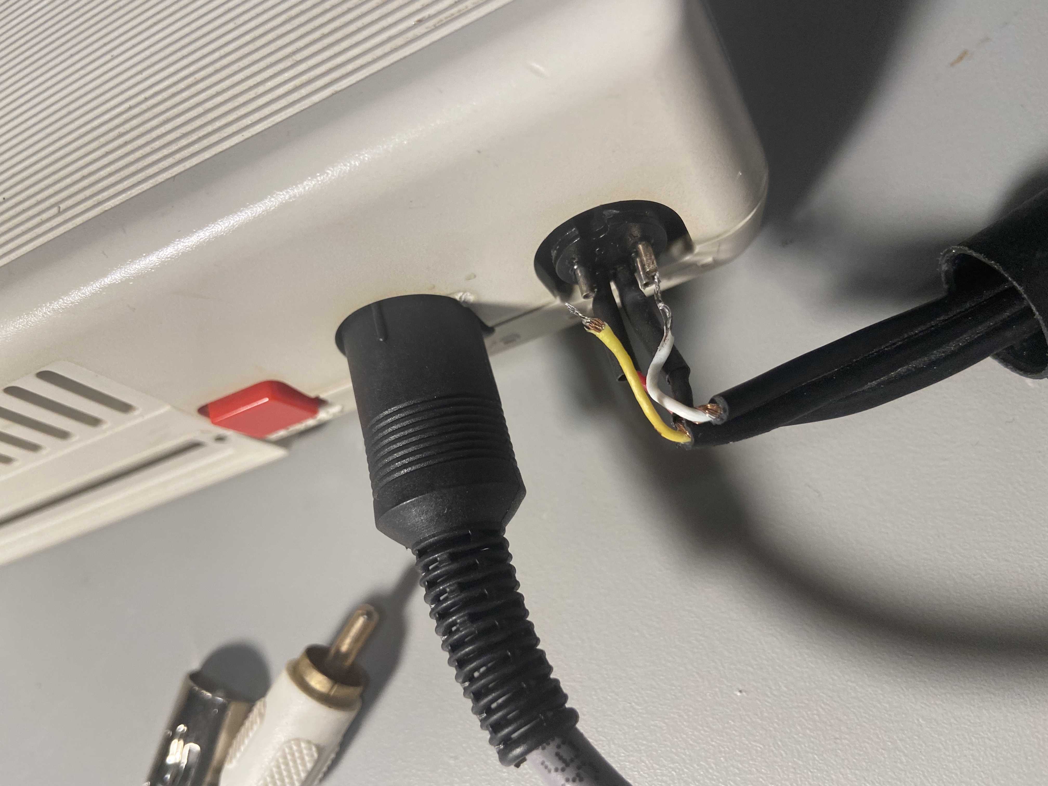
I started working on a BASIC game for the MC-10. Previously, I had been able to use the MC's serial port to "LPRINT" any BASIC programs to my Mac. Of course, this did not work anymore, since I had to change the serial cable wiring. So, I had to make a little adapter to make the serial port cable work with the BASIC ROM functions. Very frustrating.
After I got that working I had a decent build chain to write a BASIC game, doing as much of the programming as possible on the MC-10 and saving to my Mac. The line editor for the MC-10 is non-existant, but there are some solutions out there. Still it took a long time for me to write a simple mine-sweeper type game that was based on my TS-1000 efforts in a previous Retrochallenge. As much as I despise the keyboard on the TS-1000, the BASIC implementation is quite good with some conditional printing syntax that is lacking in the traditional MS BASICs. But I enjoyed figuring out how to work around the shortcomings in the MC-10 BASIC. I know there are a number of minesweeper games out there for the MC-10, but they don't seem to work on an unexpanded 4K RAM MC-10. Anyway, I have a working first version that is pretty fun to play. I intend to add a second level before the end of RetroChallenge. I used a few of the tricks that I learned on the TS-1000 to keep memory down. I was also proud of how it only has code for 2 loops - one to loop through the locations on the game board and one to loop through the 8 locations surrounding the current selection. The loops call different subroutines to do the work on each square on the grid based on a preset variable. Probably horrible coding practices, but it kept the number of code intensive for-next loops down to a minimum. Screenshot:

You can find it on my MC-10 Cassette Server.
Day 6:
I mostly played MC-10 games from Jim Gerrie's TRS-80 MC-10 Files repository. So much stuff in there! Unfortunately Google Drive reports a lot of errors when trying to play the files online. It often forces me to download the cassette audio file which is annoying, but it pretty much works. I played a game "rocket" which is basically an Apollo lunar lander simulator. I spent so much time trying to land and win the game... I finally did it though!

I have to give it up for Jim Gerrie who keeps all of this archived, and ported or wrote many of the games. So much fun, even with 4K of RAM still!
On that note, I have been thinking of the best route to upgrade this little MC-10. There are a lot of good semi-commercial options out there, but I think I will go for something far more ridiculous and excessive. If you follow my blog, you probably have some idea of what I am thinking. I am working out some schematics to figure out the best way to do the upgrade from only the expansion port. Stay tuned!
Day 5:
I spent a fair bit of time today downloading and running TRS-80 MC-10 games and utiliites. Unfortunately, the process was rough:
To be fair, many of the zip files already have a .wav format file in there, but it is still not a convenient process. XRoar is esptecially time consuming as the cassette menu controls can be a bit awkward and the conversion is done using MC-10 commands in MC-10 time. There is apparently a Windows utility to do the conversion, but I don't have Windows and it is not open source. Fortunately, I am familiar with the useful c2t utility by datajerk for converting Apple II format files to .wav and .aiff formats. I knew that the MC-10 cassette audio format was vaguely simlar to the Apple II (FM encoding), so I made some changes to make a simple command line tool for converting .c10 files to .wav files. I was so shocked when it worked, I had to double check a few times that I was playing my generated file rather than a comparison file I was using. I just posted the project code on github.
Even with the .c10 format files converted to .wav, I was still struggling with my Mac always importing them into the Music app, or not being able to rewind and start again with the Finder preview. Inspired by the Online Apple II Game Server, I uploaded the .wav files onto Google Drive, and wrote a small web app to organize and display them. So, now I can just hook up my audio cable, go to the MC-10 Cassette Server webpage, and play them right from there. I can even use an iPhone or iPad to connect. I will be adding more files and information there as I test everything.

Day 4:
I found an MC-10 serial terminal program "COMPAC" online and was able to load it onto the MC-10 using my new 'cassette' interface cable (see part 1 and part 2 of making the cable).
Of course, I could only send letters from the MC-10 to my Mac's terminal program, but not from the Mac to the MC-10. I knew immediately that it was due to the serial cable wiring and how the Tx and CD wires were swapped for printing. I tried to make a little adapter, but it did not work, so I had to re-solder the connector using the orinal pinout in the Service Manual.
Well, it works now! I can type messages back and forth between my computers finally! It's only 300 baud, but it feels like a good success. Oh, in the README for the console program was a link to a 90's awsome MC-10 website on triod. What flashback and a great resource!
Tomorrow I will see if I can access the macOS shell.

|

|

Pinout:
3.5mm TRRS plug
|   |
-----
  |   = (5) MIC + 10K OHM resistor to ground
  _
  |   = (2) Signal Ground
  _
  |   = (N/C) right EAR
  _
  v   = (4) left EAR or AUX
BASIC after the break...

So basically, MC-10 can load from Mac, but can't save cassette/audio output to Mac yet. XRoar is converting file formats for me.
Half working audio cable still in development.
BASIC program after the break.


Here is the transferred BASIC for this post:
10 CLS 20 PRINT "I MADE AN MC-10 SERIAL CABLE TODAY. FRANKLY, I AM SURPRISED THAT IT WORKED." 30 PRINT "THE RX LINE IS APPARENTLY WRONG IN THE SERVICE MANUAL. OR WRONG IN THE BASIC ROM?" 40 PRINT "ANYWAY, IT IS STRANGE THAT THE SCHEMATIC DOES NOT FOLLOW THE SCI (SERIAL COMMUNICATIONS INTERFACE) OF MC6801 EITHER" 50 PRINT "I CANT FIND AN OFFICIAL SOURCE FOR HOW IT SHOULD BE WIRED BUT IT WORKS FOR SENDING ANYWAY." 55 REM END : REM "END HERE FOR FIRST PAGE" 60 PRINT "SO I CAN TRANSFER MY BASIC PROGRAM TO MY MAIN COMPUTER NOW" 70 PRINT "THE ONLY ISSUE IS THAT IT SENDS WITH CARRIAGE RETURN ONLY AND NOT A LINE FEED." 80 PRINT "EASY ENOUGH TO FIX WITH THE TR COMMAND ON MY MAC." 90 PRINT "HOWEVER THE BASIC ROM DOES NOT HAVE A COMMAND TO LOAD FROM SERIAL PORT. SO I NEED TO MAKE AN AUDIO CABLE STILL." 100 PRINT "A PRINTER WOULD BE NICE TOO..." 110 REM END : REM "END HERE FOR SECOND PAGE" 120 CLS 130 PRINT "QUICK TIP: MAKE SURE THE CONNECTORS ARE PLUGGED INTO A SPARE JACK WHEN SOLDERING TO ENSURE THAT THE PINS DONT MOVE." 140 PRINT "IN THE END, I USED THE PINOUT IN THE ANNOTATED DIAGRAM HERE: 150 LLISTBetween running RetroChallenge and how limited the TRS-80 MC-10 is, a real endurance challenge is not in the cards for me. But I fully intend to use this computer daily, connect to some important peripherals and make some necessary upgrades. I hope the results will be a usable guide for somebody who is just getting started with the Radio Shack Model MC-10 TRS-80 Micro Color Computer. For such a small computer, it has a very long name! So, here we go with my notes so far:


SBCs + Keyboards!! I will figuring out how to interface keyboards with some 6502/6809 SBCs, playing around with PS/2 interfaces, and, if I have time, build my own parallel ascii keyboard.

Update! Change of plans... I just bought a Radio Shack TRS-80 MC-10 and I am going to spend the month using it, connecting it, and upgrading it!

After figuring out the location of the video output on the MBC020's P4 connector (pin 20), I noticed that the video and ground signals are also connected to some large through-hole pads nearby. These may be solder points for a video coax cable, or some sort of connector.

I hoped to avoid soldering directly onto the board, so I first tried some "9mm Through-Hole Loop Test Points". These fit nicely in the holes in the board, but I struggled to get them connected to a coax video cable. Withe the added weight of a cable, they pulled out too easily and were generally awkward to solder and secure.
The obvious choice for this was a PCB mount RCA/phono jack for the composite video. Unfortunately, there was just no clearance on the front of the board since an IC and the board ejector interferred with the placement. Only after my failure with the test points did I realize that, after bending up one of the ground legs, there was plenty of space on the back of the board:

|

|
With the RCA/phono jack inserted, I booted it up. The video displays "SE" until the serial connection is made, and then is shows the exact same information as the terminal. Unfortunately, some testing uncovered that the top 1/4-1/2 of the screen has some apparent tearing and sync issues which improve progressively down the screen. The bottom 1/2 of the screen is very clear 80 column output. I am not sure why this is happening, but I would assume it is a damaged component on the board. Moving around the video jack to get a better connection did not improve the video quality. Since this monitor has proven to be compatible with many vintage video devices, if there is a compatibility problem I think it must be the board that is way out of spec.

So, video is almost working.
Next, I tried adding the unmodified Mikul 6218 board with extra RAM installed in place of the usual ROMs. Although I did not test the I/O, the RAM addition worked great! Using SERVOMON commands, I was able to edit memory areas that were previously unassigned. This confirms my belief that the Mikul 6218 is a really nice and reasonably priced memory board for a variety of EXORbus systems, especially because the memory sockets are very configurable for a variety of RAM and ROM chips.
Next time I will document the memory map further and check out the keyboard connection to try to make it a complete terminal!

