 I haven't tested anything yet, but it should be fairly easy to implement. It is basically backwards data flow from my previous adapter.
Monday, July 31, 2017
Disk II Drive to USB Adapter
My CJMCU FT232H Module arrived today! Less than $10 for a FTDI FT232H break-out board / USB to SPI adapter. Really excited as it makes my AII-SPI-DSK even cheaper. In addition, I started thinking about an adapter that will allow me to rip Apple II disks right from a Disk II 5.25" drive!
 I haven't tested anything yet, but it should be fairly easy to implement. It is basically backwards data flow from my previous adapter.
I haven't tested anything yet, but it should be fairly easy to implement. It is basically backwards data flow from my previous adapter.
Monday, November 7, 2016
RetroChallenge Epilogue and Apparent Success
After Review of my plan and schematics, I noticed a small error in the Eagle schematic I posted earlier.
- Pin 11 of the socket must be connected high (or to pin 12, or to a soft switch to enable video scanning on row E of RAM).
- Pin 11 of IC F2 must be disconnected and that line (not the IC pin) must be connected to ground instead (See my hand-drawn schematic).
 |
 |
| F2 IC with pin 11 sticking out in a socket with pin 11, 12 connected | It boots! |
It seems to have worked! The computer shows the APPLE ][ greeting just as expected. I need to connect a keyboard and a disk controller card to test it all out and verify that all 48K is being accessed.
So, I now have an Apple II with 48K of 4164 DRAM in just one bank of RAM. Now for 64K. Or 128K...
 |
| 2 banks of RAM installed for future 128K modifications |
Tuesday, November 1, 2016
Final Push and Failure
I ran jumpers wires on the back of the Apple II+ logic board to route the various signals I needed (PHI_0, AX, A14&A15) to the J1 socket area. Fortunately since only half of J1 is used by the Apple II+, I can use the unused pins of that socket to route my signals through to the new circuit I am adding.
Here is my circuit diagram:

and the adapter board:
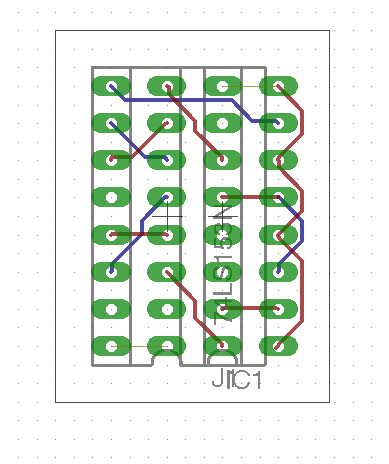
Warning - I don't know if this works yet.
After I ran the wires, I started trying to solder a tiny adapter board to translate the 74LS257 signal locations to the new 74LS153 IC. That was taking too much time for something that might not work at all, so I put the circuit on a bread board. Here it is:

Unfortunately, this did not work. I suspect that the dip jumper cable may be too long and adding some capacitance or delay. Or, the RAM timing may have been thrown off by the internal logic of the new IC. My Apple II+ is not booting and is in a similar state to when the RAM was in the wrong row. I'm sure I would have figured this out, but Halloween took priority.
Better news is that my Apple IIb is in a pretty final state. I think I will start buying supplies to actually build it.

Until next time, RetroChallenge!
Saturday, October 29, 2016
Apple II+ 64K RAM Refresh and Addressing
I managed to add my modifications back to the Apple II logic board to get the 4164 RAM enabled. It seems to be working! However, I want to address all 64K of the RAM, not just 16K. To do that, I need to refresh the extra RAM rows, multiplex the RAM row and column address for the new RAM address pin, and make sure that row C of RAM stays enabled instead of selecting row C, D, or E. See the detailed plan of attack by clicking below.
Friday, October 28, 2016
Troubleshooting Frustrations
I spent a number of hours last night and tonight trying to figure out why my modified Apple II+ was not beeping, and instead showing a screen full of question marks (or sometimes a white screen) on start-up, even after I added a row of 4264 DRAM. I swapped all of the ICs back and forth with my functioning Apple II+ and still had the same problem. At that point, I realized that I should have done some basic testing before I modified the logic board. I removed my modifications, and still had the same problem.
I found out that I could get very similar symptoms on my working Apple II+ if I removed the F2 74LS139 decoder, which selects which RAM bank to use. So I started checking continuity on my non-working board. I discovered that here wasn't continuity between the low bank selection line and the row that I had my RAM in. I thought I had found a major fault in the board. Then it hit me. The apple II+ rows are labeled A through K, and start with A on the bottom ROW. I had put my RAM in row E (the high address bank), instead of row C (the low address bank). I moved the RAM chips and after swapping out a bad chip, BEEP, and APPLE ][ at the top of the screen.
I felt so dumb. Hours wasted. So now I'm re-doing my modifications. Still time for some progress tonight. At least it's working. That logic board has't been fully functional in probably 30 years.
Tuesday, October 25, 2016
Apple II+ RAM Replacement - Power
Replacing the RAM in my Apple II+ has become a bit of a project in and of itself. Sure I could just buy some 4116 (16K bit) DRAM, but that's not very exciting, and its not an upgrade. So, Instead, I have been figuring out how I can use 4264 (64K bit) DRAM in its place. There are a lot of considerations that need to be made including power, refresh circuit, and addressing the new RAM. The descriptions below are for an RFI Revision 01 board, and may be different for other revisions. Click below to see the details of re-routing the RAM power lines and my preliminary results.
Sunday, October 23, 2016
Apple II+ Logic Board Repairs
Here are the two Apple II+ logic boards that I have for repair. They were mostly stripped of integrated circuit chips, and even have some ports and connectors that were de-soldered to repair other boards (back in the 1980's).

I chose to repair the board on the left due to the missing D6 RAM socket on the other board and a possible damaged trace under the F8 ROM.
I swapped the power connector and added a missing audio jack. These are still available on eBay as "panel mount mono jack":


A word of caution. I have found that the solder on these old boards has the potential to make you feel sick and hung-over. Drink some milk before you solder and work in a very well-ventilated area.
I was able to replace most of the missing IC on the board from the box of spares I had, and from the other board. I have no idea if they work, so that will probably require a lot of troubleshooting.
The only IC I could not replace from old pulls was the one labeled "9334" in the J14 position. Fortunately, this IC can be replaced by a 74LS259, which I had on hand from my early experiments with my SPI based Disk II emulator.
Finally, I did not want to have to troubleshoot with old, possibly bad RAM, so I have some 64K 4264 DRAM chips on hand to see if I can replace the original 16K 4116 chips. This will require some modifications to the logic board (due to the different power requirements and slightly different pinouts), which I hope I can complete before the end of RetroChallenge.
Sunday, October 16, 2016
Apple IIb Model
Added power supply and logic board texture. Color change to be Apple II+ olive-beige rather than Lisa tan-beige.


Saturday, October 15, 2016
Feet and Boots!
 |
The parts donor Apple II+ I am trying to repair is really a mess. Even the rubber feet were harvested for another computer. Fortunately, I found some decent rubber feet on eBay. I bought two packs of 12 20mmx20mmx8mm and it is a great replacement part for Disk II and Apple II feet. |
Regarding my other project, I was pretty scared to connect the repaired IIGS Upgrade board to a power supply, half expecting everything to start smoking. It boots! First time in about 15 years:
 |

|
| Composite video works | and RGB works! |
Apple ][b Refinements
Coming along nicely. I used a more period appropriate keyboard layout, and I think it improved the over-all aesthetics. That's the kind of keyboard I would be using anyway.
I am thinking, I might make this an Apple ][b -> IIGS upgrade, since the IIGS logic board is looking so good. I could also use the internals of an AppleColor RGB monitor that I have for the IIGS.


Thursday, October 13, 2016
Apple IIGS Repairs
Here are the fruits of my labor for the past two weeks. I had already attempted to repair this Apple IIGS Upgrade board, after a battery explosion did a lot of damage to the board and chassis. However, I wasn't really satisfied with how it was working out. I purchased some copper tape, and I am impressed at the way it worked to replace the traces. Much flatter and smoother, like it should be. A couple of resistors replaced and I tinned it all. Then, a lot of continuity testing. I bought some UV cure solder mask and after some time in the sunshine and under a UV light, it looks pretty good. Not perfect, but considering the terrible damage inflicted on this board, I am impressed!
The Hakko soldering iron definitely made this possible. I am afraid to hook up the power supply though...
 |
| Trace repairs and new SMT resistors in R193 and R14 locations. |
 |
| Trace repairs and new battery holder. |
 |
| Copper Tape, UV cure Solder Mask, and a weird spatula thing. |
Tuesday, October 11, 2016
Some Progress, Some Distraction
I spent some time last week working on a Google Sketchup rendition of my hypothetical Apple IIb. The idea is to solve some of the problems with the Apple II+ as a incremental update. It is clear from the Apple II+ design that some of these fixes were deliberately removed from the design late in the process, possibly to keep cost down and possibly because the Apple III was on the horizon. For instance, the odd keyboard decoder arrangement and missing switch clearly contemplated lowercase and a keypad, but the final design did not include either. Here are my specs:

 So, that's the progress. The distraction is work on my Apple IIGS Upgrade. Rather than take on another project (Apple II+ logic board), I decided to dive head first into fixing the IIGS. After replacing some of my previous repairs with copper tape, and a lot of soldering, it looks pretty good. The solder mask is curing under UV light, so I will have pictures tomorrow.
- 80 columns. This is difficult without a full terminal card, which was how most Apple II+s were upgraded.
- Upper/lower case keyboard. Shouldn't be too hard, other than a new character ROM.
- Separate keyboard with numeric keypad. This didn't catch on until after the Apple III, but it should be a relatively easy addition.
- Integrated disk drives.
- Integrated monitor. I'm indifferent here. Although I really think the Tandy TRS-80 Model III and Apple Lisa are some of the best looking retro computers.
- Two serial ports, and a parallel port. This just requires a few expansion cards.


Wednesday, September 21, 2016
RetroChallenge 2016/10 Entry
RetroChallenge 2016/10 snuck up on me due to the new start month.
For my entry I would like to focus on the Apple II+.
- First, I want to try to revive an old parts donor Apple II+ which is missing a lot of pieces and ICs.
- Next, I would like to start work on designing the Apple ][b, a computer that could have been released by Apple circa 1979. The b is for business! An incremental release of the Apple II+.
Monday, March 21, 2016
Apple IIe RAM diagnosis
I have an old, un-enhanced Apple IIe that that would give me errors while trying to load disks, like: UNABLE TO LOAD PRODOS or NO BUFFERS AVAILABLE . Now that I know a lot more about the Apple IIe (and electronics in general) than when I put it in mothballs, I tried my hand at fixing the problem again.
I recently learned that by holding down the closed (filled) apple, while turning on the un-enhanced Apple IIe, it will do a self diagnosis. Here were the results:
RAM: F13 F12 F11 F10 F9 F8 F7 F6
This indicates that every built-in RAM chip was bad (or that the unenhanced Apple IIe can not distinguish which chip is bad). I didn't quite believe this could be true, so I tried replacing some of the ICs around the RAM... to no effect. So, I splurged on an ebay auction for a set of "MICRON MT4264-10 64K 100NS DRAM". I replaced all of the RAM chips, and my un-enhanced Apple IIe sprang to life for the first time in 25 years! As it turned out, only 2 of the RAM chips were bad, but they both failed in a way that would cause the self-diagnosis to report that all of the RAM was bad. Anyway, based on my machine having 2 chips that failed in the same way, I think it must be a relatively common problem.
Now all this thing needs is a "V" key and a replacement key switch. I think the V key is around here somewhere...
Monday, February 22, 2016
Apple II Development
I am pretty amazed at the current rate of development of new Apple ][ conveniences and devices. It is worthwhile to look up from a project to see what others are doing every once in a while.
VGA adapters for the Apple IIc and IIGS seem to be hot right now.
The Nishida Radio Disk II adapters are gaining more and more features, including a nice looking web interface!
Big Mess O' Wires had added Apple II support to the Floppy Emu Disk Emulator.
It's impressive to have a microcontroller with more power than the Apple II strapped on the back of it. Although it does feel like cheating sometimes...

I merely managed to find a switch that perfectly fits the Apple II keyboard encoder for enabling lowercase once the character ROM is updated. It is labeled "ONLEDA MTS-202" and is a knock-off of some old high-quality switch, I'm sure. Good ebay search terms : Right DPDT toggle switch. Just take note of how the pins are oriented to make sure you get the right ones. I'm putting mine away for a rainy day.

A new style of Apple II prototyping card popped up on ebay too. Had to buy one.
Saturday, February 13, 2016
USR-WIFI232 and ADTPro Continued...
I really wanted the standard ADTPro Ethernet connection to work properly so that I don't have to start the ADTPro Server from the command line. Unfortunately, that connection type adds a byte to the start of the ADT packet indicating the packet number. That seems appropriate for the UDP protocol that is used, but that one byte confuses the Apple II client enough that it immediately reports an error. Commenting-out the code that adds the packet number byte allowed me to get everything working, at the expense of out-of-order packets not getting re-ordered. Not a great solution, but it is more convenient now. Really, ADTPro Server just needs a decent interface for its SerialIP mode.
Full details on the ADTPro Support Forum (Archived on the Wayback Machine).
I really like this USR-WIFI232 compared to an Apple II ethernet card. It is compatible with anything that uses the Apple SSC card, has a nice web interface for configuring it, and includes WiFi, at a little over 1/2 the price. Unfortunately, the user guide can be a bit hard to decipher.
Tuesday, February 9, 2016
USR-WIFI232 and ADTPro
Based on my testing, the USR-WIFI232 appears to work fairly well with ADTPro giving yet another option for disk transfers. However, you have to set ADTPro to use Virtual Serial over IP (localhost mode). Open the ADTPro.properties file that gets created (using a text editor, such as TextEdit) and enter the IP address and Port number of your USR-232-WIFI. Quit ADTPro, run it again, and it will connect! I set my USR-WIFI232 device to use the following UART setting from the web interface: 9600,8,None,1,Enable,Disable,Disable, and set complimentary settings on the Super Serial Card (<ctrl-a>14B). ADTPro seems to like 8 data bits, which prevents you from using the USR-WIFI232 AT commands.
I used the ADT Serial Pacing setting of "Pacing: 1000" to get a reliable connection for bootstrapping. I don't think the speed settings are tested with a TCP connection to a real Apple //e.
Once the bootstrapping is successful and ADTPro is running, it was necessary to change the UART settings of the USR-WIFI232 via the web interface to: 19200,8,None,1,Enable,Disable,Disable, as ADTPro only runs at higher speeds.
| Uart Setting | |
| Baudrate | |
| Data Bits | |
| Parity | |
| Stop | |
| CTSRTS | |
| 485 mode | |
| Baudrate adaptive (RFC2117) | |
Set the CONFI(G) in ADTPro to 19200 Baud Rate as well. After that was completed, I was able to transfer directory data, and a disk with ADTPro on it!
If the bootstrapped ADTPro gives an error INSERT SYSTEM DISK AND RESTART -ERR -1 when you restart your USR-WIFI232 (due to the hardware handshake, I think), just hit <ctrl>-<reset>, then type 800G<enter> to restart ADTPro.
Monday, February 1, 2016
Final RC2016/01 Thoughts
After some testing, I figured out that the reason I have to run everything at 300 baud has more to do with the screen redraw and processing speed of the Apple //e than the serial card. It's interesting that the Apple SSC manual derisively mentions that "Some printers are slow and do not provide a printer busy, or handshake signal to the Apple II." It provides a setting to delay after a Carriage Return for the printer to move back across the page. This is very similar to what is happening to the Apple //e which loses the first few characters after a line feed
In the mean time, I have a slow server and a new way to communicate with the Apple //e. I also have a nice color monitor, and I have a little more insight into Steve Jobs. Finally, I have a few more project ideas (KIM-//e, more Apple on the web stuff) for future retro challenges. RC2016/01 complete!
Sunday, January 31, 2016
Truly Wireless Now
 In a quest to make my Apple //e truly wireless, I did some soldering this morning to create a cable to go directly from the Apple Super Serial Card to the USR-WIFI232. This allowed me to get rid of the bulky DB-25->DB-9 adapter, and a short DB-9 cable to go from the adapter to the USR-WIFI232 (see photos). Then, I used double-stick tape to mount the USR-WIFI232 on top of the Apple //e power supply. The Apple //e already has a pop-out that fits the antenna and power supply cord fairly well. The result is an internal WIFI adapter! I suppose I could get the power for the adapter from the Apple power supply, but I'd rather not run the risk.
I really like this set-up as connecting to the Apple over serial cables always meant finding the right cables and adapters, or a null modem. They would inevitably get unplugged for another project or to move the computer.
There is a lot of potential for this configuration for transferring disk images with ADTPro. I have to use 300 baud for the Apple BASIC interpreter to keep up, but it looks like higher baud rates will work in the terminal mode of the SSC, or with a compiled program. Come to think of it, you could even have a web page on the Apple //e that accepted disk image uploads.
This is a simple, and inexpensive ($40 on ebay) alternative to some of the other Apple Ethernet products out there. Some people have done similar things with a Raspberry Pi, but, again, this is pretty much plug and play and includes WIFI.
Having made two web servers out of old Apples, I am finding that it would be a lot more interesting to make a web browser. That will probably be a future project.

Saturday, January 30, 2016
Apple //e Webserver Running!
I have my Apple //e BASIC web server running!... sort of. Try it out. Be gentle and patient, it's only 300 BAUD!:
http://162.232.186.125:8899
Code after the break.. Update: minor change in code to allow OPTIONS method
Subscribe to:
Posts (Atom)