Thursday, June 30, 2022

Synertek MBC020 Serial Snags

Serial Cable

I spent a few minutes continuity testing the P3 card edge connector for the serial port so that I could build a serial cable for the MBC020. I was hopeful that this was just a 1:1 pinout for a card edge to DB-25 RS-232 IDC connector, like one I built for my Motorola MC68000 Educational Computer Board. It is almost exactly right except the send (TxD) and receive (RxD) data lines are swapped. I thought maybe it was wired as a DCE device, but in fact, only the data lines are switched. As annoying as this was, it wasn't too difficult to put a twist in part of the ribbon cable, swapping wires 3 and 5:

Card Edge to DB25 serial cable

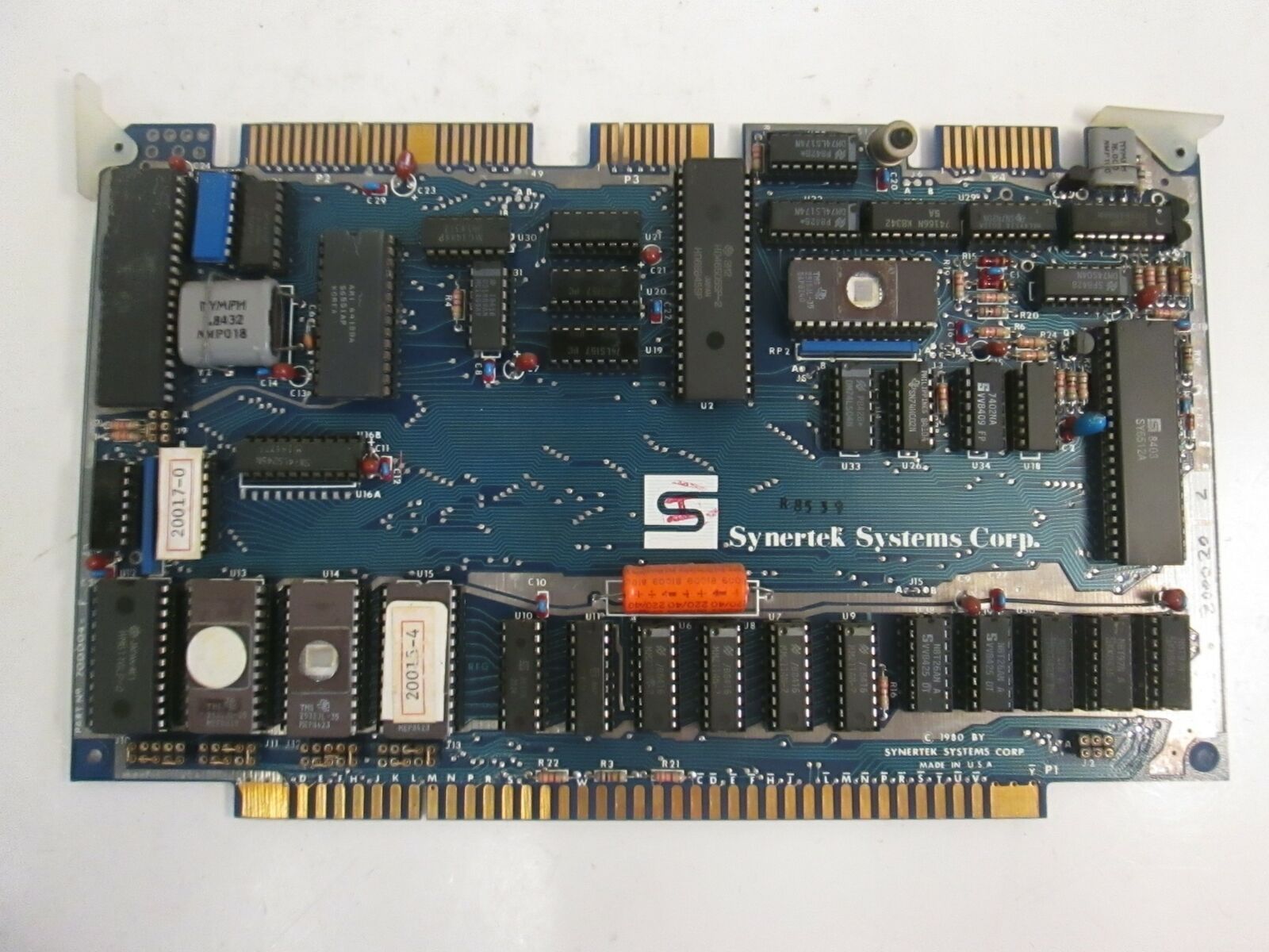
Note the twist in the green, yellow, and orange wires near the DB25 connector on the bottom right of the picture.

Serial Output

With the serial cable constructed and a null modem adapter attached, it was time to power it up! I installed the card in my EXORbus "MULTI-PLANE" backplane, and booted it up. Unfortunately, no matter what baud rate I tried, I was only receiving data that looked like a baud rate mismatch. I double checked the MBC020 driver source code in mame to see if it provided any hints, and sure enough, it apparently set 9600 baud, 7 data bits with 2 start bits. This effectively eliminates a high bit 7, as you would also need in the Apple II monitor. However, after apparently configuring GNU screen, it still did not work. Examining a hex dump of the output showed: 00000000: 00d3 c5d2 d6cf cdcf cea0 d6c5 d2a0 b4ae ................ 00000010: b08d 8ac3 cfd0 d9d2 c9c7 c8d4 a0ca d5cc ................ 00000020: adb1 b9b8 b3a0 d4cf d2d1 d5c5 a0d3 d9d3 ................ 00000030: d4c5 cdd3 a0c9 cec3 ae8d 8abe c800 ..............

This appeared to be the data I wanted, but bit 7 was still set high, making the text unreadable. After a quick check of my screen command line parameters, I realized that screen expects the serial options to be comma separated. Duh! The command:
screen -L /dev/cu.usbserial 9600,cs7,cstopb
did the trick perfectly and allowed me to finally interact with the real SERVOMON monitor:
SERVOMON VER 4.0 COPYRIGHT JUL-1983 TORQUE SYSTEMS INC. >V 0000-000F 0000 BF BF 9F BF BF BF 9F BF,B8 0008 9F AF BF BF BF BF BF BF,80 0B80 >F 00,0000-00F >V 0000-000F 0000 00 00 00 00 00 00 00 00,00 0008 00 00 00 00 00 00 00 00,00 0000 >J 1 MPC DIGITAL DRIVE REV 4.0 JUL-1983. AXES FOUND ON-LINE : 4 Ok AUTO ER 00 >G SERVOMON VER 4.0 COPYRIGHT JUL-1983 TORQUE SYSTEMS INC. >

Success! Next I will test out composite video output! Special thanks to "andysa" on the 6502.org Forum for sharing his notes on this board with me.

Wednesday, June 15, 2022

Synertek MBC020

I recently acquired a Synertek MBC020 EXORbus single board computer, notably sporting a 6512 microprocessor. The 6512 is software compatible with the famous MOS 6502 processor used in the Apple ][. This is one step closer to the whole point of this blog! It may at first seem odd that this 6512 board uses the EXORbus card edge which was most commonly associated with Motorola MC6800, MC6802, and MC6809 processors. However, the 6500 family was always intended to be MC6800 bus compatible. In fact, Rockwell even produced an AIM 65 Expansion Motherboard that would allow their AIM 65 computer (which like the Synertek SYM-1, was a derivitive of the famous MOS KIM-1 6502 trainer) to use EXORbus card modules. Synertek also made a clone of the MC6800 based Motorola MicroModule MM01, named the MBC01A2, and various EXORbus RAM and I/O cards.

Any of these ExorBus systems I have seen are either trainers or PLCs (programmable logic controllers) for industrial applications. They appear in knitting machines, industrial ovens, industrial food processing machines, and silicon wafer exposure and inspection stations. Fittingly, the Synertek MBC020 is usually seen configured for use in an "EG&G Torque Systems" servo controller. This is the same configuration for the card I purchased:

The Synertek MBC020 MOS 6512 based Single Board Computer

In a strange stroke of luck, this board happens to be available in the MAME emulator (formerly:"Multiple Arcade Machine Emulator"). I'm not sure why an industrial controller would be included in a emulator focused on arcade and console video games. Anyway, the ROMs available online appear to be the same as my own, so it is nice that I can see what I should be expecting when booting the board. Once I compiled MAME and added the ROMs, I was greeted with:

After a bit of trying out different key combinations, I discovered that the commands are predictably very similar to the SYM-1's SUPERMON monitor. Here is an incomplete summary:

SERVOMON COMMANDS: [] is optional parameter, $ is a hex digit (0-9,A-F)
Command and FormatDescription
M [[$$,]$$$$[-$$$$]]MEM: Memory examine, modify, [search,] hex data editor starting at address [-end]
R REG: Examine and modify user registers PC,S,F,A,X,Y
G [$$$$]GO: Restore all user registers [except PC=address, S=FD] and resume execution.
V [$$$$[-$$$$]]VER: View/Verify display data and checkums [starting at address [-to end]]
D [$$$$]DEP: Deposit hex data to memory [starting address]
C [$$,]$$$$[-$$$$]CALC: Calculate two's complement [-displacement], with [,offset]
B $$$$,$$$$-$$$$BMOV: Move data to address, from start -to end
J $JUMP: Restore user registers, except PC=listed entry in jump table, S=FD, and jump to it
J 1 MPC DIGITAL DRIVE REV 4.0 JUL-1983.
AXES FOUND ONLINE : 1
Ok
SD $$$$-$$$$SDBL: Store double byte from address -to address
F $$,$$$$-$$$$FILL: Fill data, from memory address -to address
S1 [$$$$]Save ASCII data to memory [starting address].

Next post: let's try out the real board!

Sunday, June 5, 2022

MIKUL 1MiB Mods (final)

It did not take long for me to realize that the virtual address jumper board for my MIKUL 6218 was not a great long-term soloution. It was ugly and was not very physically secure with jumper wires running everywhere. Instead, I decided to remove the jumper board and add a 2*5 pin header to the top of the memory board, where it belonged. As a result, I would need to program a GAL to go back in place of the jumper board, handling the conversion from virtual to physical addresses. Since I now have a working GAL programming pipeline, this was no longer a serious impediment.

Header

Adding the pin header was a simple matter of drilling holes in the board in a .10" grid, supergluing a 2*5 male header (with latch) to the board, adding some copper tape connected to ground, and soldering on jumper wires connecting to the A16-A20 address lines. Although I would have preferred to use some mounting screws on the header, both of the mounting holes ended up right on top of VCC traces.

GAL Program

With the board soldered up, I had some initial success using it with my CMS 9639 and Microware OS9 Level 2. However, I soon noticed that there was a block of memory that was not being identified at $C000-$DFFF every 64K. This is an odd range of addresses to have a problem with, since it can't be attributed to bad connections on an address line or two. I quickly identified that the GAL in U10 will disable the RAM and enable the I/O in that range, regardless of the state of the high virtual address lines. Although this is fine for the MIKUL 6809-5 board it was designed for, it is not consistent with the CMS9639's expectation that I/O is only enabled in the $00FF60-$00FF9F address range. So, I had to reprogram the U10 GAL and make some adjustments to the program in the U13 GAL to get everything working properly.

Conclusion

Here is the final product, a relatively clean looking 1 MiB EXORBus RAM and 3xVIA I/O card working great with the CMS 9619 and OS9 Level 2 on the CMS 9639: