Showing posts with label Apple II plus. Show all posts

Tuesday, November 13, 2018

Using the Apple II as a 28C16 EEPROM Burner

This is a tutorial on how to use an Apple II with a Super Serial Card as a 28C16 EEPROM programmer. For the purposes of this tutorial, I will be giving instructions on programming a lowercase character ROM for the Apple II+ Rev 7. You can use an earlier Apple II for general EEPROM programming though. The simplest way to transfer the data from a binary file to the EEPROM without extra hardware is to use the Mac's headphone port connected to the Apple II Cassette input port, and that method is what I will demonstrate here. Alternatively, you could use a virtual disk, TCP/IP card, or another Super Serial Card to transfer the data to the Apple II.

Supplies:

  • Apple II+ Rev 7 (minimum to accept the finished lowercase character ROM)
  • Apple Super Serial Card (SSC)
  • Atmel 28C16 EEPROM
  • ROM binary file
  • Macintosh running OS X

Process:

Install c2t on your Mac
c2t will convert a binary file to the audio format that the Apple II can use. You can find instructions to install on the c2t GitHub page. However, due to an HTML redirect and a typo, some of the instructions did not work correctly for meThe instructions are now correct, and I had to use the Terminal commands:
sudo curl -L https://github.com/datajerk/c2t/raw/master/bin/c2t >/usr/local/bin/c2t
sudo chmod 755 /usr/local/bin/c2t
Get and convert the ROM binary file to audio format

Apple ROM files are fairly easy to find. Once the archive is downloaded to your Downloads folder, extract the files and convert to audio using the Terminal commands:

open ~/Downloads/APPLE+II+ROMS.zip
cd ~/Downloads/APPLE\ II\ ROMS/APPLE\ II+/
c2t -2 APPLE\ II+\ -\ LOWERCASE\ CHARACTER\ GENERATOR\ -\ 2716.bin,8000 ~/Downloads/LOWERCASE_ROM.aif

This creates an audio file in your Downloads folder named "LOWERCASE_ROM.aif", which can be used to transfer the ROM data to your Apple II. This audio file is available for download, if you want to skip installing c2t.
Modify the Super Serial Card

The Apple SSC manual documents how to modify the card to accept an SRAM chip, which is compatible with the pinout of a 28C16 EEPROM. I have a clone of the SSC which is slightly different and will allow me to easily enable and disable this function.

First, I removed the ROM (the lower big chip) so I didn't accidentally damage it. Then, I cut the traces that link the some of the vias in the center of the card, and removed the solder in the vias.

These vias correspond to the bow-ties and solder pads on the SSC card. I soldered in gold and silver double row header pins so I can easily see which pins should be jumped at the same time.

If you have an SSC, card just cut the bowties and solder across the jumper pads, according to the instructions in the manual. Note that you will have to undo this modification to use the original SSC ROM

With the pins soldered in, I can use jumpers to configure the card for the original ROM, for EEPROM, and to set the write enable separately for the EEPROM (black jumper cap).

Now, install the 28C16 EEPROM into the ROM location (double check the orientation of the EEPROM chip!) and insert the card into slot 2 of the Apple II.

Connect the Computers
Use a 3.5mm Male to Male Audio Aux Cable to connect the Mac headphone jack to the Apple II Cassette Input port. The cable can can be stereo or mono, although stereo is easier to find nowadays. Turn the Mac volume up to the maximum level.
Transfer and Write the ROM Data

It would be really simple if we could just transfer the audio data directly into the memory locations of the EEPROM. Unfortunately, I was unable to do this. I believe that the EEPROM needs more time to write than is given to it by the Apple II Monitor, so maybe the faster AT28C16E would work better for direct writing. I could only successfully write about 16 bytes at a time reading audio or copying directly to the AT28C16.

Instead, we will copy to the Apple II memory, then slowly POKE it into the EEPROM using AppleSoft BASIC. On the Apple II, assuming 64K of RAM:

] CALL -151
* 8000.87FFR

Play the LOWERCASE_ROM.aif file on your Mac. When it is loaded, you should hear a beep on the Apple II, and get another * prompt.

At this point, you could try directly copying to the EEPROM by:

* CFFF
* C200
* C800<8000.86FFM
* C200<8700.87FFM
But, I received errors when verifying:
* C200<8700.87FFV

So, if that doesn't work, let's load an AppleSoft BASIC program to get the data into the EEPROM. To load it, return to BASIC by hitting:

<CTRL><RESET>
Enter the BASIC command:
] LOAD
Then use the Mac to download and play the audio file for the ROM transfer BASIC program or, skip the LOAD command and enter it by hand:

5 REM ?"TRANSFER BIN FROM $8000 TO SSC CARD"
10 S = 2 : REM ?"SLOT 2, DO NOT USE 0, 1, 3" 
20 LM = 49152 + (S*256) : REM ?"SLOT IOSEL"
30 HM = 51200 : REM ?"$C800"
40 ST = 32768 : REM ?"$8000"
50 X=PEEK(53247) : REM ?"$CFFF"
60 X=PEEK(LM) : REM ?"ENABLE HM"
70 BL = 1792 : REM ?"IOSEL SIZE"
80 LM=LM-BL
100 FOR X= 0 TO 2047
110 V= PEEK(ST+X)
120 IF X < BL THEN EA = (HM+X) : GOTO 140
130 EA = (LM+X)
140 POKE EA,V
150 ? EA; ": ";V
160 NEXT X
170 ? "TRANSFERRED ";X;" BYTES" 
200 END
After the beeps, run the loaded BASIC program:
] RUN
This will slowly write the data you previously stored in the $8000 memory range to the I/O shared $C800.$CEFF range, and the slot 2 $C200.$C2FF range. The process should take less than 2 minutes (1 min 45 secs). You can edit the BASIC program to change slots if you need to, but don't use slot 1 on any Apple, or slot 3 on an Apple //e, as the IOSEL area we are using is not normally addressable in those slots.

Once the program runs, turn off the Apple II, remove the EEPROM and insert it into the "ROM_SPCL" location at the bottom of the logic board (double check the orientation of the EEPROM chip!). You will normally have to disassemble the computer case to reach down there.

Monday, November 5, 2018

64K 4164 DRAM Decoding Integration

I integrated the 4164 DRAM decoder wiring into the logic board this weekend. It was very difficult to troubleshoot, and on retrospect, I think an adapter board would have been easier and less problematic. The main hangup was that the A14 signal to pin 10 of the J1 socket is connected on both sides of the logic board. One side in from expansion slot 7, and the other side goes out to H1 socket which creates the (A14&A15) signal. I had routed the (A14&A15) back to the J1 socket to decode the upper 16K of RAM. After disconnecting the A14 line from pin 10 and re-connecting pin 10 to a new video decoder signal (HIRES&PAGE2), the video decoder signal was getting sent through to H1 to give (HIRES&PAGE2&A15), which is wrong and caused computer to not be able to access the ROM.

Anyway, I fixed the problems and 74ls153 now sits in the J1 socket like it was always supposed to be there. The signals to decode the upper 16K of memory in the 4164 DRAMs are now available. I need to build circuit with registers to set to enable the upper bank and bank switch the 4K that overlaps the I/O area of the Apple II+. It will basically be 1/2 of an Apple 16K RAM/Language card.

Wednesday, April 18, 2018

Apple II "The Keyboard Company" Keyboard Repair

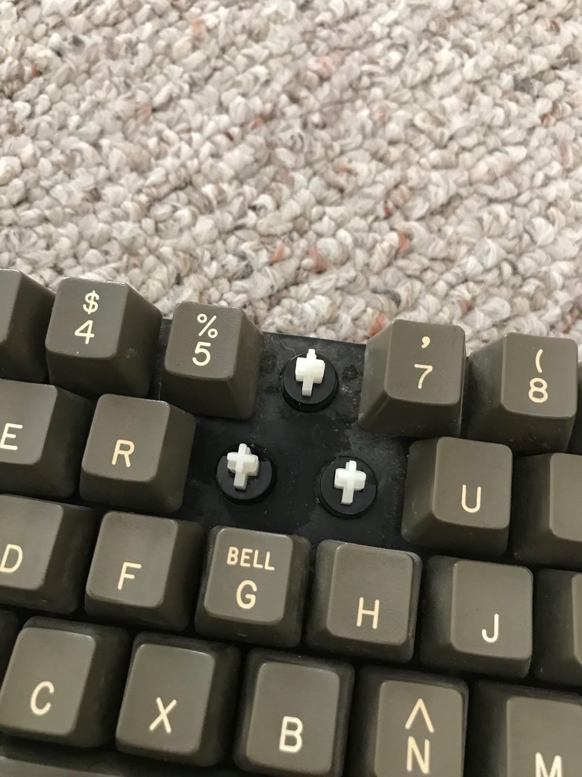
During my recent move, one of my Apple II+ computers didn't fare so well and broke 2 key posts. I really don't like the keyboard in this particular computer: it sticks, it often misses key strokes, and the feel is not very good. I didn't know how different the keyboard was until I took it apart and found... no Alps key switches! But, since Apple II+ keyboards are not cheap, I paid a few bucks for replacement key posts instead of replacing the keyboard. Process:

  1. Unscrew and remove the base plate of the computer
  2. Unscrew and remove keyboard
  3. Unscrew a bunch of tiny screws to remove the circuit board from the keyboard
  4. Push the broken post out the back
  5. Push in the new post
  6. Reassemble
  7. Continue hating how the keyboard feels

One repair completed!


Weird spring / contact matrix
I tried to repair the posts, and the one on the left worked OK, but I ended up replacing both of them.
6 and T are fixed!

Monday, November 7, 2016

RetroChallenge Epilogue and Apparent Success

After Review of my plan and schematics, I noticed a small error in the Eagle schematic I posted earlier.
  1. Pin 11 of the socket must be connected high (or to pin 12, or to a soft switch to enable video scanning on row E of RAM).
  2. Pin 11 of IC F2 must be disconnected and that line (not the IC pin) must be connected to ground instead (See my hand-drawn schematic).
I figured out problem 1 first. But when I booted I received half of a startup beep repeatedly, like it was stuck. It took a while until I realized I forgot Problem 2 since it was only on my older schematic. I used an IC socket and connected pin 11 and 12 and raised the IC leg. This is important as it decodes whether the Apple II is in RAM or I/O mode. The computer was stuck with no access to I/O or ROM (or simultaneous access to RAM and I/O or ROM).
F2 IC with pin 11 sticking out in a socket with pin 11, 12 connected It boots!

It seems to have worked! The computer shows the APPLE ][ greeting just as expected. I need to connect a keyboard and a disk controller card to test it all out and verify that all 48K is being accessed.

So, I now have an Apple II with 48K of 4164 DRAM in just one bank of RAM. Now for 64K. Or 128K...

2 banks of RAM installed for future 128K modifications


Tuesday, November 1, 2016

Final Push and Failure

I ran jumpers wires on the back of the Apple II+ logic board to route the various signals I needed (PHI_0, AX, A14&A15) to the J1 socket area. Fortunately since only half of J1 is used by the Apple II+, I can use the unused pins of that socket to route my signals through to the new circuit I am adding.

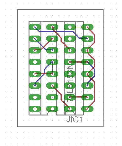
Here is my circuit diagram:

and the adapter board:

Warning - I don't know if this works yet.

After I ran the wires, I started trying to solder a tiny adapter board to translate the 74LS257 signal locations to the new 74LS153 IC. That was taking too much time for something that might not work at all, so I put the circuit on a bread board. Here it is:

Unfortunately, this did not work. I suspect that the dip jumper cable may be too long and adding some capacitance or delay. Or, the RAM timing may have been thrown off by the internal logic of the new IC. My Apple II+ is not booting and is in a similar state to when the RAM was in the wrong row. I'm sure I would have figured this out, but Halloween took priority.

Better news is that my Apple IIb is in a pretty final state. I think I will start buying supplies to actually build it.

Until next time, RetroChallenge!

Saturday, October 29, 2016

Apple II+ 64K RAM Refresh and Addressing

I managed to add my modifications back to the Apple II logic board to get the 4164 RAM enabled. It seems to be working! However, I want to address all 64K of the RAM, not just 16K. To do that, I need to refresh the extra RAM rows, multiplex the RAM row and column address for the new RAM address pin, and make sure that row C of RAM stays enabled instead of selecting row C, D, or E. See the detailed plan of attack by clicking below.

Friday, October 28, 2016

Troubleshooting Frustrations

I spent a number of hours last night and tonight trying to figure out why my modified Apple II+ was not beeping, and instead showing a screen full of question marks (or sometimes a white screen) on start-up, even after I added a row of 4264 DRAM. I swapped all of the ICs back and forth with my functioning Apple II+ and still had the same problem. At that point, I realized that I should have done some basic testing before I modified the logic board. I removed my modifications, and still had the same problem.

I found out that I could get very similar symptoms on my working Apple II+ if I removed the F2 74LS139 decoder, which selects which RAM bank to use. So I started checking continuity on my non-working board. I discovered that here wasn't continuity between the low bank selection line and the row that I had my RAM in. I thought I had found a major fault in the board. Then it hit me. The apple II+ rows are labeled A through K, and start with A on the bottom ROW. I had put my RAM in row E (the high address bank), instead of row C (the low address bank). I moved the RAM chips and after swapping out a bad chip, BEEP, and APPLE ][ at the top of the screen.

I felt so dumb. Hours wasted. So now I'm re-doing my modifications. Still time for some progress tonight. At least it's working. That logic board has't been fully functional in probably 30 years.

Tuesday, October 25, 2016

Apple II+ RAM Replacement - Power

Replacing the RAM in my Apple II+ has become a bit of a project in and of itself. Sure I could just buy some 4116 (16K bit) DRAM, but that's not very exciting, and its not an upgrade. So, Instead, I have been figuring out how I can use 4264 (64K bit) DRAM in its place. There are a lot of considerations that need to be made including power, refresh circuit, and addressing the new RAM. The descriptions below are for an RFI Revision 01 board, and may be different for other revisions. Click below to see the details of re-routing the RAM power lines and my preliminary results.

Sunday, October 23, 2016

Apple II+ Logic Board Repairs

Here are the two Apple II+ logic boards that I have for repair. They were mostly stripped of integrated circuit chips, and even have some ports and connectors that were de-soldered to repair other boards (back in the 1980's).

I chose to repair the board on the left due to the missing D6 RAM socket on the other board and a possible damaged trace under the F8 ROM.

I swapped the power connector and added a missing audio jack. These are still available on eBay as "panel mount mono jack":

A word of caution. I have found that the solder on these old boards has the potential to make you feel sick and hung-over. Drink some milk before you solder and work in a very well-ventilated area.

I was able to replace most of the missing IC on the board from the box of spares I had, and from the other board. I have no idea if they work, so that will probably require a lot of troubleshooting.

The only IC I could not replace from old pulls was the one labeled "9334" in the J14 position. Fortunately, this IC can be replaced by a 74LS259, which I had on hand from my early experiments with my SPI based Disk II emulator.

Finally, I did not want to have to troubleshoot with old, possibly bad RAM, so I have some 64K 4264 DRAM chips on hand to see if I can replace the original 16K 4116 chips. This will require some modifications to the logic board (due to the different power requirements and slightly different pinouts), which I hope I can complete before the end of RetroChallenge.

Saturday, October 15, 2016

Feet and Boots!

The parts donor Apple II+ I am trying to repair is really a mess. Even the rubber feet were harvested for another computer. Fortunately, I found some decent rubber feet on eBay. I bought two packs of 12 20mmx20mmx8mm and it is a great replacement part for Disk II and Apple II feet.

Regarding my other project, I was pretty scared to connect the repaired IIGS Upgrade board to a power supply, half expecting everything to start smoking. It boots! First time in about 15 years:
IIGS Upgrade board and composite video IIGS Upgrade board and RGB video
Composite video worksand RGB works!

Wednesday, September 21, 2016

RetroChallenge 2016/10 Entry

RetroChallenge 2016/10 snuck up on me due to the new start month. For my entry I would like to focus on the Apple II+.
  • First, I want to try to revive an old parts donor Apple II+ which is missing a lot of pieces and ICs.
  • Next, I would like to start work on designing the Apple ][b, a computer that could have been released by Apple circa 1979. The b is for business! An incremental release of the Apple II+.

Monday, February 22, 2016

Apple II Development

I am pretty amazed at the current rate of development of new Apple ][ conveniences and devices. It is worthwhile to look up from a project to see what others are doing every once in a while.

VGA adapters for the Apple IIc and IIGS seem to be hot right now.

The Nishida Radio Disk II adapters are gaining more and more features, including a nice looking web interface!

Big Mess O' Wires had added Apple II support to the Floppy Emu Disk Emulator.

It's impressive to have a microcontroller with more power than the Apple II strapped on the back of it. Although it does feel like cheating sometimes...

I merely managed to find a switch that perfectly fits the Apple II keyboard encoder for enabling lowercase once the character ROM is updated. It is labeled "ONLEDA MTS-202" and is a knock-off of some old high-quality switch, I'm sure. Good ebay search terms : Right DPDT toggle switch. Just take note of how the pins are oriented to make sure you get the right ones. I'm putting mine away for a rainy day.

A new style of Apple II prototyping card popped up on ebay too. Had to buy one.